
Schematic diagram of the heating system. Schemes and drawings of heating
A schematic diagram of a heating system is the simplest diagram with which you can quickly and inexpensively mount a high-quality and durable heating system. But when implementing a project, you should know a few important rules and features, without which you simply cannot cope with the task.
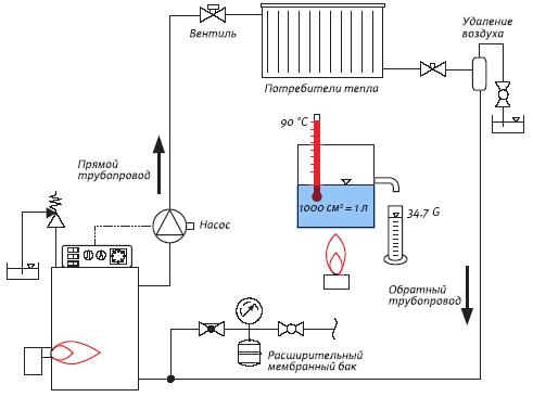
So any circuit diagram consists of boilers and pipes (in the article we will talk about autonomous systems). The principle of operation of such a scheme is as follows - the coolant is heated in the boiler and, using a circulation pump, is supplied through the pipeline to the heating radiators. Having given off heat to the room, the coolant returns along the return circuit to the boiler and everything repeats. It turns out that the simplest scheme is based on cyclic processes.
Heating schemes
Water heating is the most common option for heating rooms of any type. In most cases, the role of the coolant here is played by water, which is supplied from the boiler to heating radiators.
In general, experts distinguish between two types of water systems:
- With natural water circulation (when pressure is formed in the circuit itself);
- With forced circulation (water enters pipes and radiators using a circulation pump).
In any circuit diagram, it is mandatory to have:
- Heating boiler (any type);
- main riser;
- reverse riser;
- Pipeline;
- Return pipeline;
- Radiators.
So, today the following basic heating schemes are known:
- With bottom and top wiring;
- With horizontal wiring;
- Single-pipe;
- Two-pipe.
Top wiring

In this scheme, the coolant is heated in the boiler and, due to its density, rises along.
Attention!
This scheme provides for expansion tank at the highest point of the heating system.
Further, through the pipeline (which, by the way, should go at a slight slope), the coolant enters the hot risers. These risers stretch from the top floor of the house to the first and run along the entire height of the building. The spent coolant, in turn, is simply displaced hot water and on the "return" returns to. To regulate the level of hot water supply at the outlet to the radiators, special shut-off valves are installed.
Bottom wiring

A system with a lower wiring has a main (supply) pipeline that provides coolant to all other risers below the level of residential premises. As for the return risers, they are connected to a common "return", carried out even lower.
Note!
This scheme contains in its structure an air line located on top.
With its help, all the accumulated air in the radiators is automatically removed, which in turn is discharged through the expansion tank.
Two-pipe systems

In any two-pipe scheme, both at the top and at the bottom, the heated water rises and enters the radiators through the pipeline, where it cools over time and becomes heavier. Through the return risers, the cooled coolant flows into the return pipeline and returns to the boiler. Cold water has a greater density and mass than hot water and thus displaces it into the pipeline itself, creating natural circulation even without a pump.
Single pipe systems

At its core, this is the simplest scheme (see photo), which even an inexperienced person can make and mount with his own hands. It differs from a two-pipe one in that, having given up its heat on the upper floor, less is transferred to the lower one. It turns out that the coolant, overcoming floor after floor, gradually cools and it turns out that the inhabitants of the first floor receive the least heat. In order for the inhabitants of the lower floors to simply not freeze, the engineers added additional ones for the inhabitants of the lower floors.
Also, the problem can be partially solved by installing special jumpers on each radiator. With jumpers, part of the hot water passes to the floor below without cooling.
It should be noted that the main riser in a single-pipe system must be protected as reliably as possible from heat loss. Otherwise, the system will lose not only heat, but also the power of water pressure, which will negatively affect the heating of the house as a whole.
As for the return line, it is the other way around - it cannot be isolated in any case! This is due to the fact that more cold water has more weight and, accordingly, displacing hot water, creates more force.
Single-pipe schemes with a horizontal flow system

This scheme is attractive in that all radiators on the floor are connected in one line. The main advantage of such a system is the ease of installation. Also, you will need significantly less pipes and risers.
If we talk about the shortcomings, then the main one is the tendency of such a system to cause air jams. This problem can only be solved by installing automatic air release valves (Maevsky valves).
Note!
For those who do not know, the circuit diagrams do not contain any measuring characteristics, but only show what is connected to what and shows an approximate "strapping" of the house.
Circulation methods - which one to choose

Now, as for the circulation method, which scheme to choose? Natural or forced?
As for the natural circulation of the coolant, then there are perhaps more minuses than pluses.
- Natural circulation is not amenable to automatic regulation;
- For its arrangement, pipes with a large diameter are needed, the price of which is noticeably higher;
- Not very aesthetically pleasing in the interior;
- You can only adjust this system with your own hands - in the boiler you can only increase the flame when it's cold, or vice versa reduce it when it gets hot.
If you live in regions where unexpected power outages are commonplace, then these systems are ideal for you.
This scheme does not provide for any additional (electrical) devices and devices:
- Security group devices;
- bypass valves;
- Electrical temperature sensors;
- Fuel regulators, etc.
- Another disadvantage of this scheme is a much larger amount of fuel consumed for the heating season.
As for the pros, in essence this is the most reliable scheme that can last up to 40 years without repair! It is extremely reliable and does not depend on any voltage drops. In general, apart from the boiler, there is basically nothing to break in it.

Forced circulation is convenient and comfortable for residents of those regions that do not suffer from power surges. In this case, the system is regulated both manually and automatically - for each room you can set a personal temperature, exclusively for your needs.
But in automatic systems there are some disadvantages - not every local installer will be able to mount a complex circuit with all the sensors and complex connections you need, and hiring a non-resident specialist is quite expensive.
Also, at its core, this system is very gentle and will not work for a long time in a house where there are power outages.
Summarize
Having considered all the options, it will be easier for you to make a decision and make it really right choice based on your living and financial conditions. We have a detailed video instruction that will cover all the issues in more detail and help you understand the intricacies of circuit diagrams.
The price of equipment is different, so there is no unequivocal opinion and cost - each boiler and each circuit require an individual calculation, but it should be said right away that it will cost you a serious "penny". Good luck!
Schemes and drawings of heating
Contents: Why they do it What is calculated Example of a detailed calculation There is no doubt that most homeowners will agree with the statement that an independent heating system is in many ways superior to district heating. Many people want to heat their homes on their own. The main reason for this desire lies in creating the optimal combination: warmth-comfort and savings. Even despite the costs that are inevitable during the initial installation, in ...

Contents: What determines the cost of heat Costs for a boiler of 20 kW. Electric Oil Gas Heating firewood Useful tables As practice shows, the heating system is not only a source of warmth and comfort in a private house, it is also the cost of fuel and maintenance, as well as cash injections for its construction. The main guideline that...

Contents: Collector scheme Advantages of the collector Serial Advantages of the serial The performance of the equipment connected to the water supply system depends on the correct installation. It is important to choose the right water supply scheme for the apartment, which will ensure timely water supply from the central water supply to all points of analysis. At the same time, it is necessary to ensure sufficient water pressure for the correct operation of all plumbing equipment and household appliances. In real...

Contents: One-pipe system Schematic: Single-pipe horizontal Schematic: Single-pipe vertical Two-pipe system - Schematics Wiring heating system in a private house can be made different ways. And the owner is required to decide which method would be preferable in this particular case in order to solve the issue of heating the room with a strictly limited budget. A single-pipe heating method in a private house is considered ...

Content: Why is it needed? The principle and scheme of operation The main elements of the device Today it is impossible to imagine your life without heating. Even in the last century, the most popular was the oven. Not many people use it these days. The main disadvantage furnace heating is the cold floor. All the air rises and thus the floor is not heated. Technological progress has come a long way...

Contents: The main parameter is power Calculation of the required number of sections Among a large number consumers, the most popular heating device is the radiator. In its own way, it is a classic version of the heating system equipment. The battery is a hollow element that is filled with a substance - a coolant, whose role, as a rule, is played by water. When choosing a radiator, it is necessary to pay attention to several technical factors, ...

Contents: When to change: in winter or summer Sequence of work Connecting to a one-pipe system Connecting to a two-pipe system Over time, the efficiency of the heating system decreases and it becomes necessary to replace one or another component. Independent replacement of parts of the heating system on the shoulder of anyone, it is enough just to have theoretical knowledge in this issue and tools needed for the job. The most common reason for replacement...

Contents Standard wiring Scheme of a single-circuit system If you need a warm floor In order for your house to be heated constantly and at no extra cost, it is necessary to approach the design of the heating system as responsibly as possible and choose the most competent solution. In this case, everyone faces the choice of the most optimal option with the available financial capabilities, in addition, a lot will depend on ...

Contents: Scheme of a one-pipe system Scheme of a two-pipe system No matter how the world changes, and technology, many people still associate private houses with a one-story building. Perhaps, Soviet stereotypes have taken root in many, or the time has simply come when it is necessary to control your expenses for building materials, as well as the amount that it will cost ...

Contents: What to consider when choosing a boiler? Calculation of the power of a heating boiler Which pipes are better to take for installation Calculation of the required number of radiators When building a house or reconstructing a residential facility that has been in operation for several years, it is necessary to adhere to the standards prescribed in the project documentation. Among the mandatory documents is the calculation of the heating of a house or other residential building, ...
Rating: 4 855
Before installing the heating system in the house, it is necessary to design it. When (diagrams and drawings) it is important to make them with the appropriate symbols.
This is necessary so that during further operation you can navigate the functioning system. Being guided in it, you can easily find a breakdown and carry out its repair as soon as possible, as you will know the causal relationship between the components of the heating system.
Conventions
There are special programs that help to properly design the heating system of your home. Each has its own conventions. They serve to ensure that everyone can understand the drawing.
And accordingly, for general accessibility and ease of reading the map of the heating system, each component is indicated by a certain letter marking:
- "P" - supply systems, exhaust systems, installations of systems;
- "B" - system settings;
- "U" - air-type curtains;
- "A" - heating units.
These designations will be used for elements of the heating system.
The following symbols will be used to calculate the forced heating system:
- "ST" - OS water riser;
- "GST" - the main water riser of the OS;
- "GV" - horizontal branch;
- "K" - compensator.
The heating system as a whole will be called "OS".
The diagrams present us with a heating system with the above markings. On the plan, OS are shown as dots.
Their diameter is about 2 mm. Heating systems in section, its drawings or diagrams are reproduced in the following scales:
- Ventilation and heating installations
- Scheme-placement, plan - 1 to 400, 1 to 800
- Sections and plans - 1 to 50, 1 to 100;
- Ventilation message and OS:
- Sections and plans - 1 to 100, 1 to 200
- Fragments of sections and plans - 1 to 50, 1 to 100;
- System nodes - 1 to 20, 1 to 50;
- Schemes - 1 to 100, 1 to 200;

Schematic diagram of heating
When designing the above data in detail, scales are used - 1 to 2, 1 to 5, 1 to 10. OS are not designed separately. More precisely, their separate image is not found. Most often, one drawing, a diagram combine an image of a heating system, ventilation system and indoor air conditioning systems.
Image types
For due Maintenance on the plans it is necessary to provide for the presence of images of alignment parallels and the length between them, the main platforms and the finished floor covering on the floor, the diameter of the section and sewer communications, the air circulation system. It should also be displayed how many heating fluids and what is the length of the radiators and many other equally important details.
Drawings and diagrams of the heating system, and as we have already found out, the rest of the communications can be made in different versions of axonometric projections. For people closely studying drawing and geometry, there will be no problems with the concept of axonometry. However, for those who are far from this area of knowledge, we present the transcript.
An axonometric diagram (or projection) for heating is one of the ways to display geometric objects in a drawing using parallel projections. Divided into three types - isometric projection, dimetric and trimetric. By the number of axes - equal to three, identical two and distorted three. This is how plans for heating systems with other communications are carried out.

Axonometric diagram
Give the name of the drawings as follows. When the scheme is executed at a certain height of the building, it is called the "Plan at around 3 thousand". Performing a drawing for heating a floor gap, he is given the name "PLAN 2-5 floors". And the completed drawing of one floor of the house, but on different planes, will be called "PLAN 2-2" or "PLAN 6-6", etc.

Plan of the 2nd floor of a one-pipe system
Heating systems and other communication messages (ventilation, air ducts, water supply) are reproduced in one of the types of axonometric projections. This is an isometric frontal diagram. The components of the systems are indicated by conditional graphical values.
If the length of the placement of the OS, air duct, water supply system is large and complexly designed, then they will be shown in the drawing with gaps.
Graphic symbols represent all components of the heating system. When depicting a heating system, all diameters of pipes of any supply, their degree of inclination (slope), the number of risers and their dimensions, and much more are taken into account.
If a heating drawing is drawn up apartment building, then the main heating system is displayed only the one that is underground. For the ground part of the building, a wiring diagram for heating risers, wiring for heat-carrying pipes and batteries is drawn up.
Planning in the heating ventilation system includes the following indicators: diameter of air ducts, volume of air capacity, number of pipes and more.
Manholes and openings in the air duct or ventilation necessary for repair work or measurements and air samples are also displayed on the general diagram of the heating system. Their brand is also indicated. Drawings of the heating system should include all kinds of details and features of the pipeline, building, partitions, etc. all this is necessary for the correct subsequent operation of the OS, its repair and other necessary work. It happens that several operating systems are located and operate in one building at once. In this case, the diagram indicates its number.
The executive scheme for heating is carried out not only in general form, but also in section. They specify the rules for installing a heating system. The use of aggravating details in the scheme complicates its perception and reading. That is why the cuts of parts and their complete drawings are carried out in a simplified way, without superfluous.
It became absolutely clear that the presence of drawings showing the structure of the OS in the house is extremely necessary. To perform such a scheme, you will need to know the generally accepted symbols and letter markings, and have drawing skills. You will also need to know this in order to read the plans already made by someone, for the independent implementation of repairs.
Your contacts in this article from 500 rubles per month. Other mutually beneficial cooperation options are possible. Write to us at [email protected]