
The volume of earthworks online calculator. Calculator for calculating the pit and the volume of earthworks
2.1. Routing for earthworks.
2.1.1. Initial data for maintenance earthworks:
1. Soil - sandy loam, loam.
2. Pipes - steel GOST 10704-91 about 159x4.5
3. The length of the pipeline - l = 346 km.
4. Construction time - summer
5. Construction area - Yuzhny settlement, Barnaul
6. Physical - mechanical properties of the soil
1) Sandy loam, loam.
4) Group of soil for work:
bulldozer - I;
Single-bucket excavator - P;
2.1.2. Determining the scope of earthworks.
1. Calculation of volumes for the development of a trench.
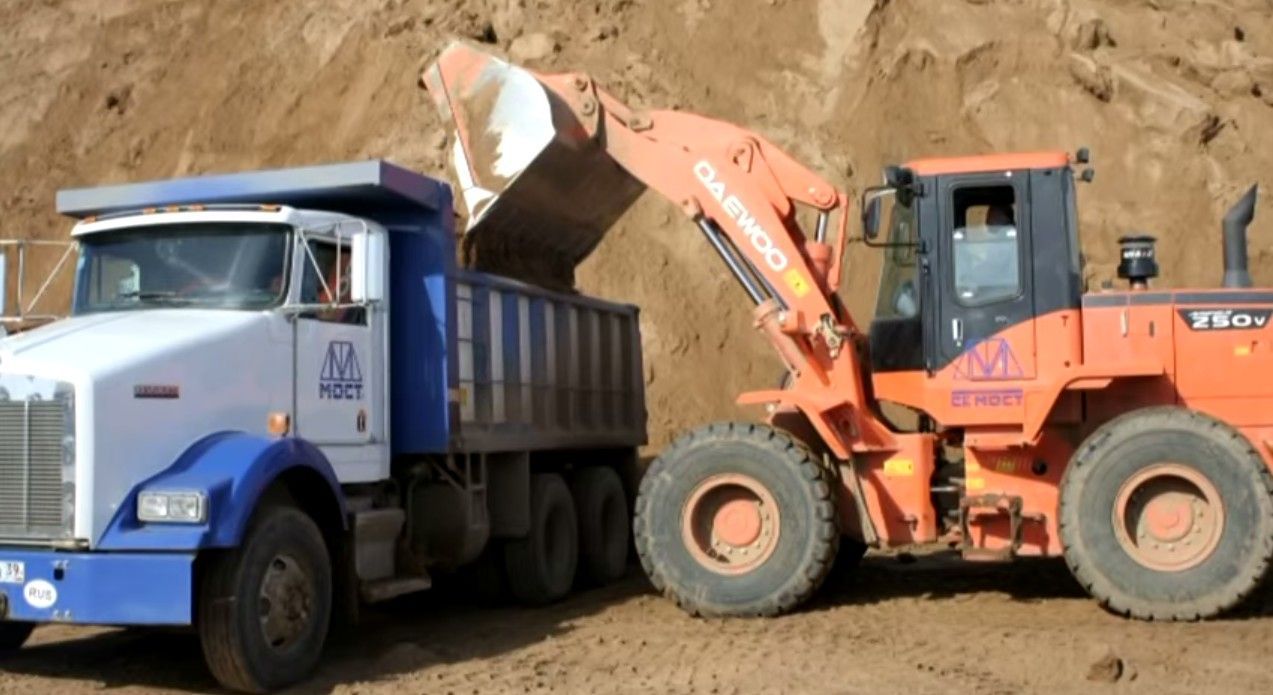
a) Trench width at the bottom:
a \u003d Æ + 2a \u003d 0.159 + 2x0.2 \u003d 0.559 m.
Due to the fact that the development of the trench is carried out by a bucket-wheel bucket-wheel excavator with replaceable equipment and a working width of 0.6 m, we accept the width of the trench below and above 0.6 m. In places where slopes are required, the vertical walls are fixed with special temporary supports, shields support stands.
d) Trench volume:
V tranche \u003d (a + B cf) / 2 * h cf * l;
where Вср is the average trench width between two pickets;
h ср – trench height average between two pickets;
l is the length of the trench section between two pickets.
Calculation of the volume of earthworks for the development of a trench.
Table 1
2) Pipe volume:
V pipes \u003d (p * d 2 * l) / 4,
V pipes (Æ 225X12.8 mm) = 148.6 m 3.
V pipes (Æ 110X6.3 mm) = 0.2 m 3.
V pipes (Æ 63X4.5 mm) = 0.25 m 3.
V pipes total. \u003d 149.05 m 3.
3) The volume of soil under the pits:
V pr \u003d 0.05 * V tranche \u003d 182.28 m 3.
4) Volume of soil for backfilling:
a) Sinus padding:
V podb \u003d V podb tranche - V pipes \u003d 948.1-149.05 \u003d 799.05 m 3.
sinus padding width on top:
In under \u003d a cf + 2 * (d + 0.2) * m \u003d 600 + 2 * 0.425 * 0 \u003d 0.6 m;
trench tamping volume:
V sub tranche \u003d (d + 0.2) * L * (A + B under) / 2 \u003d (0.6 + 0.6) / 2 * 0.425 * 1800 \u003d 948.1 m 3.
b) Backfill:
V backfill. =V sum. tranche - V pipes. - V sub sinuses \u003d 3645.546 - 149.05 - 799.05 \u003d 2697.446 m 3.
V sum. tranche \u003d V tranche + V pr \u003d 3645.546 + 182.28 \u003d 3827.826 m 3.
5) When arranging cavaliers for backfilling, its cross-sectional area is calculated by the formula:
S kav \u003d V kav / L \u003d 3237/3817 \u003d 0.848, m 2.
The volume of soil in the cavalier, taking into account its initial loosening
V cav \u003d V zas * K pr \u003d 2697.446 4.2 \u003d 3237, m 3
If the section of the cavalier is in the form of an isosceles triangle with a slope of 1: 1.5, which corresponds to the slope of the bulk soil, then the height H and the base B in m of such a cavalier are expressed by the formulas:
H= S cav /1.5=0.848/1.5=0.57, m;
H=3*H=3*0.0.57=1.7,m

6) Calculation of the volume of work on cutting the vegetation layer:
F cf \u003d A 1 * l \u003d 9.025 * 3817 \u003d 34448.425, m 2
A 1 \u003d 1.7 + 1 + 0.6 + 1 + 0.225 + 1 + 3.5 \u003d 9.025, m

2.1.3Selection of dump trucks for sand delivery when arranging the pipeline base:
a) The volume of soil in a dense body in the excavator bucket:
V gr. \u003d (V cov. * K nap) / K ave \u003d (0.12 * 0.8) / 1.2 \u003d 0.08 m 3.
where V kov is the accepted volume of the excavator bucket, m 3;
K nap - bucket filling factor, taken: for a bucket-wheel excavator 0.8 ... 1; dragline 0.9…1.15;
b) The mass of soil in the excavator bucket:
Q = V gr. *r \u003d 0.08 * 1.7 \u003d 0.136 tons.
where r is the density of the soil in natural occurrence, t/m 3 .
c) Number of buckets in the body of a dump truck:
For a transportation distance of 3 km, we choose the KRAZ-222 dump truck with a carrying capacity of 10 tons.
n \u003d P / Q \u003d 10 / 0.136 \u003d 74 buckets
d) The volume of sand in a dense body loaded into the body of a dump truck:
V = V gr. * n \u003d 0.08 * 74 \u003d 5.92 m 3.
e) The duration of one cycle of the dump truck:
T c \u003d t n + 60 * l / V g + t n + 60 * 1 / V p + t m \u003d 7.6 + 60 * 3/19 + 2 + 60 * 3/30 + 2 \u003d 27.57 min.
t n \u003d V * H in p / 100 \u003d 5.92 * 1.8 / 100 \u003d 7.6 min - soil loading time, min;
H vr - the norm of machine time, taking into account the development of 100 m 3 of soil by an excavator and loading into vehicles, machine min, determined by ENiR2-1; N vr \u003d 1.8
L - soil transportation distance, km;
V g - the average speed of the dump truck, km / h, in the loaded state, determined according to table 7;
V p \u003d 25 ... 30 km / h - the average speed of the dump truck in an empty state;
t p = 1...2 min - unloading time;
t m = 2 ... 3 min - maneuvering time before loading and unloading.
f) Required number of dump trucks:
N \u003d T c / t n \u003d 25.57 / 7.6 \u003d 4 dump trucks.
2.1.4. Selection of sets of earth-moving vehicles.
Technical and economic comparison of machine sets.
It is carried out taking into account the following indicators:
1. Cost of development of 1 m 3 of soil.
C \u003d (1.08 * SC machine. Changes + 1.5 SZp) / P change. Ex.
1.08 - coefficient taking into account overhead costs;
From the machine shifts - the cost of the machine-shift included in the set;
P change. vyp. - shift excavation of the excavator, taking into account the development of the soil and loading into vehicles;
SZp - amount wages not included in the cost of a machine shift;
1.5 - coefficient of overhead costs for wages.
P change. vyp. \u003d (8 / H vr) * 100, m 3 / cm,
where 8 is the number of hours of operation of the machine per shift;
H vr - the norm of machine time, taking into account the development of 100 m 3 of soil by an excavator and loading into vehicles, machine. hour, determined by EniR 2-1.
2. Determine the specific capital investments for the development of 1 m 3 of soil.
To ud. \u003d 1.07 / P see * (S (With opt. / T year.)
1.07 - the cost factor for the delivery of cars manufacturer to the base of mechanization;
With opt. - inventory and estimated cost of machines included in the set;
T year. - the standard number of machine shifts per year.
3. The given costs for the development of 1 m 3 of soil.
P beats \u003d C + E * K beats.
E is the normative coefficient of investment efficiency.
4. The complexity of the development of 1 m 3 of soil.
T = S T mash. cm / V ved. mash
S T mash. cm is the total labor intensity of a set of machines;
V led. mash - the volume of soil development for the leading machine.
We select sets of cars.
table 2
| I option |
P option |
| Leading machine |
Leading machine |
| Rotary excavator ETR-161 bucket capacity 0.12 m 3 |
Dragline E - 505 bucket capacity 0.5 m3 |
| For cutting vegetation |
|
| Bulldozer DZ - 18 (T-100M) |
Grader DZ - 14 (D - 395) |
| backfilling |
backfilling |
| Bulldozer DZ - 18 (T-100M) Rammers IE-4502 |
Bulldozer DZ - 18 (T-100M) Rammers IE-4502 |
| Site layout |
Site layout |
| Bulldozer DZ - 18 (T-100M) |
Bulldozer DZ - 18 (T-100M) |
Estimated cost of machines and cost of machine-shift mechanisms
Table 3
We calculate technical and economic indicators:
For the bucket wheel excavator ETR - 161 with excavation into the dump.
P change. vyp. \u003d 8 / 1.8 * 100 \u003d 444.4 m 3 / cm
C \u003d (1.08 * (44.22 + 3 * 24.5)) / 444.4 \u003d 0.28 rubles.
To ud. = 1.07/444.4*(23620/300+7210/300) = 0.25
P beats \u003d 0.28 + 0.15 * 0.25 \u003d 0.607
The data obtained is summarized in a table and compared:
Table 4
We accept for the production of works a set of machines and mechanisms of the 1st option, since the indicators of this set are more profitable and economical compared to the set of machines and mechanisms of the 2nd option.
2.1.5. Instructions for the production of earthworks.
1. Cutting the vegetative layer.
The process of cutting the vegetation layer is carried out by a bulldozer DZ - 18 based on a tractor T - 100M, with a hydraulic drive of a rotary blade. Soil is collected in a rectangular way, to a cutting depth of 0.15 m. The bulldozer movement pattern is a strip next to the strip.
Digging pattern: Bulldozer movement pattern:
  |
2. Development of a trench.
The development of the trench is carried out by a multi-bucket excavator of the ETR brand - 161. The development is carried out in a dump according to the frontal scheme, since the work is carried out in unrestricted conditions outside the buildings.
Technical characteristics of the ETR excavator - 161:
1) Bucket capacity - 0.12 m 3
2) Number of buckets - 10 pcs;
3) The greatest digging depth is 2.4 m;
4) Development width - 0.61 m;
5) highest height unloading - 5.6 m;
6) Power 86 (118) kW (hp);
7) Weight - 13.1 tons;
8) Productivity 600m per shift
Excavator slaughter scheme:
 Manual completion is carried out by a team of workers - excavators in order to remove excess soil that was not removed by an excavator from the trench and level the base. The removed soil is stored in a cavalier on the edge of the trench.
 The foundation of the trench is made by the same team - excavators to a height of 15 cm from the bottom of the trench for laying pipes.
The scheme of manual completion of the trench:

Trench foundation device.

5. Sinus padding with seal.
The lining of the sinuses is carried out in order to secure the gas pipeline in the trench from shifts and movements. The soil is taken from the cavalier. Soil compaction is carried out to a height of 20 cm from the top point of the gas pipeline. Soil compaction is carried out manually by rammers of the brand IE - 4502. The scheme of backfilling the soil into the trench is similar to the scheme of the foundation device.
5. Backfill.
Backfilling is carried out by a DZ-18 bulldozer based on a T100M tractor, with a hydraulically driven rotary blade, at an angle of 45° to the trench axis. The soil is moved from the cavalier next to the trench.
Trench backfill scheme:
 |
6. Layout.
Leveling is carried out by a DZ - 18 bulldozer based on a T - 100 tractor . Scheme of the movement of the bulldozer - a lane next to the lane. Upon completion of the planning, the soil cover is recultivated with the sowing of grasses, which must be carried out no later than one year after the completion of the work.
Movement pattern:

2.1.6. Measures for safety in the performance of earthworks.
1.6.1. General safety requirements for earthworks:
1. In order to avoid accidents and damage to machines and mechanisms, the operating personnel must know and strictly follow the safety rules.
2. A driver who has undergone special training and has received a certificate to operate the machine is allowed to operate the machine (equipment).
3. The machine (equipment) must be kept in good condition. It is not allowed to start work on a faulty machine (equipment).
4. Starting the engine should be carried out by the shift leader. Before starting, he must give a warning signal.
5. Before moving off, the driver must make sure that there are no people and foreign objects in the danger zone.
6. It is forbidden to work construction and assembly machines under the wires of operating power lines.
7. Storage of materials, movement and installation of construction machines and vehicles within the prism of soil collapse is prohibited.
1.6.2. Safety precautions for the operation of a single-bucket excavator.
1. During operation, the excavator must stand on a horizontal platform that is pre-leveled.
2. If there are people in the danger zone, it is forbidden to start the work of the excavator
3. When the engine is running, it is forbidden to carry out maintenance of the excavator.
1.6.3. Safety precautions during the operation of the bulldozer.
1. When operating a bulldozer, the following requirements must be observed:
a) stop the machine if an obstacle is encountered in front of the cutting edge of the blade that the bulldozer cannot overcome;
b) do not extend the blade of the blade beyond the edge of the slope;
c) to lower the blade to the ground during its cleaning or repair;
d) do not approach with caterpillars the edge of a freshly filled embankment closer than 1 m.
2. The machine left with the engine running must be safely braked.
3. Do not leave the bulldozer with the engine running.
4. The bulldozer driver is prohibited from:
a) Start the movement of the bulldozer without giving a warning signal;
b) Get out of the cab of the bulldozer while it is moving;
c) Take on the chest.
2.1.7. Operational quality control.
Operational control is carried out during the production process and after their completion. It is carried out by a measuring method or technical inspection. The control results are recorded in general and special work logs, geotechnical control logs.
Indicators of operational control in the development of excavations and device
natural bases*.
Table 6
| Limit deviation |
Scope of control |
|
| 1. Deviation of the bottom marks of the excavations from the design ones (except for excavations in boulders, rocky and permafrost soils) during rough development: single-bucket excavators equipped with buckets with teeth single-bucket excavators equipped with a leveling bucket, cleaning equipment, planer excavators: bulldozers trench excavators scrapers |
For mechanically driven excavators by type of working equipment: dragline +25 cm direct digging +10 cm backhoe +15 cm for hydraulic excavators: 10 cm +5 cm |
Measurement points are set randomly, the number of measurements must be at least: |
| 2. Deviation of the bottom marks of the excavations from the design ones during rough development in rocky soils and permafrost soils, except for planning shortfalls shortfalls |
are not allowed according to the table. 5 SNiP 3.02.01-87 |
If the number of measurements per site to be leased is at least 20 in the highest places established by visual inspection |
| 3. The same, without loosening boulder and blocky soils: shortfalls Busts |
Not allowed Not more than the value of the maximum diameter of boulders (blocks) contained in the soil in an amount of more than 15% by volume, but not more than 0.4 m |
|
| 4. The same, planning recesses: shortfalls Busts |
*Control method - measuring.
13. Calculation of labor costs and wages .
Table 7
| Rationale |
Name |
Volume of work |
||||||
| Time limit per hour |
Rate |
St - st labor costs |
||||||
| Cutting of the vegetative layer DZ-18 (T-100M) |
||||||||
| Development of a trench with a backhoe excavator, bucket 0.12 m 3 |
||||||||
| Foundation device in the trench |
||||||||
| Tamping of sinuses with rammers IE-4502 |
||||||||
| Backfilling by bulldozer DZ-18 (T-100M) |
||||||||
| Layout bulldozer DZ-18 (T-100M) |
||||||||
2.1.9. Material and technical resources.
Table 8
2.2 Technological map for the assembly of pipes in a thread and a butt joint.
2.2.1 Initial data for work:
2. Pipes - polyethylene (PE-80) Æ 225 X 12.8 mm, Æ 110 X 6.3 mm, Æ 63 X 4.5 mm.
3. Construction time - summer
2.2.2 Determining the scope of work.
1. Pipe length -12m.
2. Pipeline length - 3822 m.
2.2.3 Selection of hoisting and mounting mechanisms according to mounting parameters.
For the assembly and butt connection of pipes on the edge of the trench in a thread, automobile cranes are used.
Q=Pe+Sq main,
P e - weight of the mounted element;
Sq base - equipment weight (slings, traverses, etc.).
Q \u003d 102.6 + 27.3 \u003d 129.9 kg.
Mounting crane for assembling pipes in a thread on the edge of the trench: The mounting crane is selected according to the actual weight of the lowered pipe per crane, with an appropriate boom reach.
R \u003d B / 2 + a 1 + a 2 + a z + b / 2
B - the width of the trench along the top;
b - crane width;
and 2 - the width of the space occupied by the link;
and 3 - the distance from the pipe to the axis of the crane (pipelayer).
According to regulatory data, the weight of the pipes:
Table 1
To perform these works, a crane KS - 1561 with the following characteristics is suitable:
1) Estimated boom reach -11m;
2) Load capacity - 4 tons;
3) Base car - MAZ-200. Load-handling device - soft towels PM-521.
2.2.4 Instructions for the production of work.
1. Assembly of pipes into a thread.
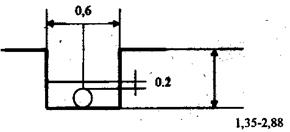
The assembly of pipes into a thread is carried out on the edge of the trench. Pipes are brought by a ZIL-131 pipe truck and stored with subsequent assembly. The number of pipes brought by one pipe carrier Æ 225 mm - 24 pieces. Pipes of smaller diameters are produced in bays. When assembling pipes into links, external centralizers are used for ease of installation of the type: TsNE-8-15 for Æ 110-160 mm; TsNE-16-15 for Æ 160-225 mm.  |
Scheme of work production:
2. Butt connection of links.
It is carried out by a team consisting of welders of 5 and 3 categories.
Butt welding with a heated tool.
Pipes are welded at ambient temperature from -15°С to +40°С. The place of welding is protected from precipitation, dust and sand. When welding, the free end of the pipe is closed to prevent drafts inside the welded pipes.
Connecting parts are welded to pipes or pipe sections in
procurement workshop at an ambient temperature of at least -5°C.
Butt welding of polyethylene pipes is performed by a Vidos-4600 SPA welding machine with a set of half rings d = 225 mm, wall thickness of at least 5 mm.
The technological process of connecting pipes and parts by butt welding includes:
Preparation of pipes and parts for welding (cleaning, assembly, centering, machining of ends, checking the coincidence of ends and gaps in the joint);
Joint welding (flashing, heating of the ends, removal of a heated tool, draft of the joint, cooling of the joint).
The sequence of the assembly and welding of polyethylene pipes.

a) Centering and fixing the ends of the pipes to be welded in the clamps of the welding machine.

b) Machining of pipe ends with the help of trimming.

c) Checking the accuracy of the coincidence of the ends by the size of the gap "C" == 0.5 mm for pipes Æ over 110 to 225 mm.

d) melting and heating of the surfaces to be welded with a heated tool

e) Joint settlement before the formation of a welded joint.
Before assembling and welding pipes and fittings, their cavities are thoroughly cleaned from soil, snow, ice, stones and other foreign objects.
The ends of pipes and fittings are cleaned of all contaminants at a distance of at least 50 mm from the ends. The ends of pipes and parts are cleaned from dust and sand with dry or moistened ends (rags) followed by wiping dry. If the ends of pipes or parts are contaminated with grease, oil or any fats, they are degreased with alcohol, white spirit, acetone.
Pipe ends that are deformed or have deep (more than 4-5 mm) nicks are cut off.
The assembly of pipes and parts to be welded, including the installation, alignment and fixing of the ends to be welded, is carried out in the clamps of the centralizer of the welding installation.
The ends of pipes and parts are centered on the outer surface so that the maximum displacement of the outer edges does not exceed 10% of the nominal wall thickness of the pipes being welded. The fitting of pipes during alignment is carried out by turning one or both pipes around their axis, installing supports under the pipes at a certain distance, using gaskets. If the difference in wall thickness of the welded pipes or parts is more than 15% of the nominal wall thickness or more than 5 mm, a pipe (part) having a greater thickness is beveled at an angle of 15 + 3 ° to the pipe axis to the wall thickness of a thin pipe (part).
When butt welding, the protrusion of the pipe ends from the clamps of the centralizers is 15-30 mm, and the welded parts are at least 5 mm.
The fixed and centered ends of pipes and parts before welding are subjected to mechanical processing - facing, in order to align the surfaces to be welded, directly in the welding installation.
After machining, contamination of the surface of the ends is not allowed. Chips are removed from the inside of the pipe or part with a brush, and burrs are removed from the sharp edges of the end with a knife. After processing, the centering and the presence of a gap in the joint are checked again. Between the ends brought into contact there should be no gaps exceeding:
0.5 mm - for pipes with a diameter of over 110 to 225 mm inclusive.
The gap between the paddle probe (GOST 882-75) with an error of 0.05 mm.
Butt welding with a heated tool consists in heating the welded ends of pipes or parts to a viscous-flow state of polyethylene in direct contact with a heated tool and subsequent connection of the ends under the pressure of sediment after removing the tool. In the process of excavation, a pit is made with dimensions of 1.2X1.0X0.7 m.
2.2.5 Selection of vehicles for transporting pipes.
Polyethylene pipes do not belong to the category of dangerous goods GOST 19433, they are transported by any mode of transport in accordance with the rules for the carriage of goods.
When packing pipes, products are used in accordance with GOST 21650. Pipes delivered to the construction site in segments are tied into packages, fastened at least in three places. When packing pipes in coils and coils, the ends of the pipes must be rigidly fixed.
Pipes fastened in packages are transported by vehicles equipped with platforms and bodies; the distance between the links on the packages is no more than 3 m. Transportation on lashes is not allowed.
When transporting pipes by road, the length of the pipe ends hanging from the body of the machine or platform should not exceed 1.5 m, coils and coils are transported on car platforms. Pipeline units are delivered to construction sites in containers in which they are securely fixed. Containers are labeled "DO NOT THROW".
Pipes during transportation are laid on a flat surface of vehicles, protecting them from contact with sharp metal parts. Transportation, loading and unloading of pipes is carried out at an outside air temperature of at least -20 °C. Dropping pipes and fittings from vehicles is not allowed.
During loading and unloading operations, it is not allowed to move pipes by dragging.
For transportation of pipes, a ZIL-131 off-road truck with a trailer carrying pipes in packages is suitable, with the following technical specifications:
The number of transported pipes Æ 225 mm - 24 pieces;
The base car is ZIL - 131.
2.2.6 Safety measures in the course of work.
1. To protect the welder from electric shock, the condition of the insulation of the electrode holder handle and all current-carrying parts and wires is systematically checked.
3. Cranes and other lifting mechanisms must be examined and tested before being put into operation.
4. During the operation of jib cranes, people should not be allowed to stay in their area of \u200b\u200baction; during the lowering of pipes, fittings, fittings and other parts into the trench and wells, workers must be removed from them
2.2.7 Calculation of labor and wages .
For all types of work, labor costs and wages are calculated.
Table 7
| Rationale |
Name |
Volume of work |
||||||
| Time limit per hour |
Rate |
St - st labor costs |
||||||
| Welding pipes on the edge of the trench |
||||||||
| 9-2-7 T2 No. 2v |
Butt Welding |
|||||||
2.8. Material and technical resources.
The need for operational materials:
Table 3
2.3. Technological map of laying the pipeline in a trench
2.3 Technological map of laying the pipeline in a trench.
2.3.1 Initial data for work:
1. Construction conditions - unrestricted.
2. Pipes - polyethylene (PE-80) 0 225 X 12.8 mm, 0 110 X 6.3 mm, 0 63 X 4.5 mm.
3. Construction time - summer
4. Construction area - Pavlovsky district.
2.3.2 Determining the scope of work.
The length of the laid pipeline is 3822 m.
2.3.3 Selection of hoisting and mounting mechanisms according to mounting parameters.
Selection of load-lifting mechanisms. According to regulatory data, the weight of the pipes:
Table 1
Pipelayers T - 614 are used for laying the pipeline in a trench, which are selected according to the same parameters as erection cranes.
Characteristics of the pipelayer T - 614:
1) Estimated boom reach - 5.53 m;
2) Carrying capacity - 6.3 tons;
3) Stability moment - 16 tf*m;
4) Basic tractor - DT-75;
5) Load lifting speed, m/min - 8.3;
6) Lowering speed , m/min - 8.3;
7) Travel speed, km/h:
forward - 3.05-6.5;
back - 2.6-3.25;
8) Main dimensions (with vertically raised boom and advanced counterweight), mm
length - 4560;
width - 3640;
height-6000;
9) Mass, t-11.9.
Load-handling device - traverses.
2.3.4 Instructions for the production of laying work.
1. Laying the pipeline in a trench.
Pipeline laying in a trench is carried out by T-614 pipelayers with a lifting capacity of 6.3 tons, the estimated boom reach is 5.53 m. Traverses are used as load-handling devices during laying. Scheme of laying the pipeline in a trench using traverses for both pipelayers:

2.3.5 Safety measures in the production of laying work.
1. Pipes, various materials and parts are lowered into the trench in a mechanized way using pipelayers. Dumping pipes and materials into the trench is prohibited.
2. Passports and individual numbers must be entered for all machines and devices, according to which they are recorded in a special log of their technical condition.
3. Pipelayers must be inspected and tested before being put into operation.
4. During the work of pipelayers, people should not be allowed to stay in their area of action; while lowering pipes, fittings, fittings and other parts into the trench, workers must be removed from them
2.3.6 Calculation of labor costs and wages.
For all types of work, labor costs and wages are calculated.
2.3.7. Material and technical resources.
The need for operational materials:
Table 3
2.4 Technological map for pipeline testing.
2.4.1 Initial data for conducting work:
1. Construction conditions - unrestricted.
2. Pipes - polyethylene (PE-80) Æ225 X 12.8 mm, Æ 110 X 6.3 mm, Æ 63 X 4.5 mm.
3. Construction time - summer
4. Construction area - Pavlovsky district.
2.4.2 Determining the scope of work.
The length of the tested pipeline is 3822 m.
2.4.3 Selection of compressor station.
1) Discharge pressure - 2.5 MPa;
2) Productivity - 12 m 3 / min;
3) Base vehicle - KRAZ-257;
4) Overall dimensions - 9.66 X 3.02 X 3.06 m;
5) Weight-21 t.
2.4.4. Instructions for the production of test work.
The gas pipeline in the city is tested for strength and density. To clean the internal cavity of pipes from scale, moisture and contaminants, they are blown before testing. Purging is carried out with air at a pressure of 7 * 133.3 Pa, for which temporary valves are installed. The gas pipeline is tested for strength with air during construction, with a test pressure of 4.5 * 10 5 Pa. The test time is 1 hour. In this case, no visible pressure drop is allowed on the pressure gauge. Defects found must be corrected prior to the density test.
The gas pipeline is tested for density with air at a test pressure of 3 * 10 5 Pa, the duration of the test is at least 24 hours. The results of the density test are considered positive if the actual pressure drop does not exceed the calculated value determined for a gas pipeline of the same diameter using the formula:
During the density test, the gas pipeline is kept under pressure for at least 30 minutes, after which, without reducing the pressure, an external inspection is carried out and all welded, flanged and threaded joints are checked with soapy water. In the absence of a visible pressure drop on the pressure gauge and no leaks during soaping, the gas pipeline is considered to have passed the test. When testing a gas pipeline during the production process, inventory plugs with rubber seals are installed.
The scheme of work performance is given in the graphic part of the technological map.
2.4.5. Measures for safety in the production of installation work.
1. Passports and individual numbers must be entered for all machines and devices, according to which they are recorded in a special log of their technical condition.
2. The compressor station must be inspected and tested before being put into operation.
3. When testing a gas pipeline with air, all shut-off, safety and relief devices must be checked most carefully.
4. When raising the air pressure in the gas pipeline, it is forbidden for people to be near the inventory plugs.
5. No work to eliminate defects in a gas pipeline under pressure can be performed.
6. At the ends of the gas pipeline being tested, there must be inventory plugs, as well as fixing lugs that absorb the forces that arise in the pipeline when the pressure rises.
7. During the test, the presence of people within the security zone is prohibited.
2.4.6. Calculation of labor costs and wages.
For all types of work, labor costs and wages are calculated.
Table 1
2.4.7. Material and technical resources.
The need for operational materials:
table 2
2.5. Technological map for blowdown
pipeline.
2.5.1. Initial data for work:
1.Construction conditions - unrestricted.
3. Pipes - polyethylene (PE-80) - Æ 225X12.8 mm, Æ110X6.3 mm,
Æ 63X4.5 mm.
3. Construction time - summer
4. Construction area - - Pavlovsky district.
2.5.2. Determining the scope of work.
The length of the purged pipeline is 3822 m.
2.5.3. Choice of compressor station.
The compressor station is selected according to its capacity, discharge pressure and mobility.
The required parameters correspond to the compressor station SD 12/25, with technical characteristics:
1) Discharge pressure - 2.5 MPa;
2) Productivity - 12 m 3 / min;
3) Base vehicle - KRAZ-257;
4) Overall dimensions - 9.66 X 3.02 X 3.06 m;
5) Weight - 21 tons.
2.5.4. Instructions for the production of purge work.
Gas pipeline purge.
Purge of the gas pipeline is carried out in two stages:
1. Filling the receiver;
2. Purging the gas pipeline.
At the first stage, one part of the pipeline is filled with air to a pressure of 1 MPa. At the second stage, the purge of the remaining part is started through the inventory purge unit.
In the process of production of works, the detected defects are eliminated.
The scheme of work performance is presented in the graphic part of the technological map.
2.5.5. Safety measures in the production of purge operations.
8. Passports and individual numbers must be entered for all machines and devices, according to which they are recorded in a special log of their technical condition.
9. The compressor station must be inspected and tested before being put into operation.
10. When testing a gas pipeline with air, all shut-off, safety and relief devices must be checked most carefully.
11. When raising the air pressure in the gas pipeline, it is forbidden for people to be near the inventory plugs.
12. No work to eliminate defects in a gas pipeline under pressure can be performed.
13. At the ends of the gas pipeline being tested, there must be inventory plugs, as well as fixing straps that absorb the forces that arise in the pipeline when the pressure rises.
14. During the test, the presence of people within the security zone is prohibited.
2.5.6. Calculation of labor costs and wages.
For all types of work, labor costs and wages are calculated.
Table 1
| Rationale |
Name |
Volume of work |
||||||
| Time limit per hour |
Rate |
St - st labor costs |
||||||
| Purging the gas pipeline (filling the receiver) |
||||||||
| Gas pipeline purge (purge) |
2.5.7. Material and technical resources.
The need for operational materials:
table 2
2.6. Technological map for a puncture.
2.6.1. Initial data for work:
1. Construction conditions - unrestricted.
2. Pipes - polyethylene (PE-80) - Æ 225X12.8 mm, Æ110X6.3 mm,
Æ 63X4.5 mm.
3. Construction time - summer
4. Construction area - Pavlovsky district;
1. Soil - loam;
2. Physical and mechanical properties of the soil
1) Sandy loam, loam.
2) Average density in natural occurrence - r \u003d 1.65 t / m 3, - r \u003d 1.8 t / m 3
3) The coefficient of initial loosening - 20% (K pr \u003d 1.2).
2.6.2. Determining the scope of work.
Puncture length - up to 90.m
2.6.3. The choice of lifting and mounting mechanisms according to mounting parameters.
Selection of load-lifting mechanisms.
For installation and dismantling of equipment for puncture, automobile cranes are used.
The lifting capacity of the crane is determined by:
Q \u003d P e + ∑q main. ,
P e - weight of the mounted element;
∑q base - the weight of the equipment (slings, traverses, etc.).
Q \u003d 102.6 + 27.3 \u003d 129.9 kg.
The mounting crane is selected according to the actual weight of the lowered equipment per crane, with a corresponding boom reach.
The estimated reach of the crane boom (from the vertical axis of rotation of the crane to the center of the trench) will be equal to:
R \u003d B / 2 + a 1 + a 2 + a 3 + b / 2
B - trench width along the top;
b - crane width;
a 1 - distance from the edge of the trench to the pipe;
a 2 - the width of the space occupied by the link;
a 3 - distance from the pipe to the axis of the crane (pipelayer).
R = 0.6/2 + 1.0 + 0.225 + 2 + 3.6/1 = 5 m
To perform these works, a crane KS - 3561 is suitable with the following characteristics:
1) Estimated boom reach - 14.5 m;
2) Load capacity - 10 tons;
3) Base car - MAZ-200.
Load-handling device - steel slings.
2.6.4. Instructions for the production of work with horizontal punching.
Piercing is carried out using a pipe equipped with a tip that is pressed into the ground.
For pressing pipes-casings into the ground during piercing, an installation consisting of two jacks GD-170/1150 is used.
Hydraulic jacks GD-170/1150 are driven by pumps high pressure grades H-403 and G-17. The transfer of pressure forces to the pipe-casing (case) being laid is carried out by clamping clamps (screw).
Installations for laying cases by piercing are mounted in working pits, 10-13 m long and 2.2 m wide and 2.5 m deep. The length of the receiving pit along the bottom is 1-1.5 m.
Vertical guide frames for laying steel cases are made of wooden beams simultaneously with the device for fastening the front wall of the working pit.
Horizontal guide frames are installed at the bottom of the working pit and are made of shortened sleepers and rails. The length of the guide frames is taken to be 1-1.5 m less than the length of the links of the casings being laid; when building up the casing to be laid with links 6 m long, the guide frames should have 4.5-5 m.
Type I thrust walls are used to transfer reactive piercing forces to the ground. To transfer pressure forces from the hydraulic jack installation to the thrust wall of the pit, support packs are used from rail segments welded together.
On the image. 1 shows a support shoe designed by the Soyuzvodokanal project for push forces up to 980 kN
2-scarf
4-rib

To transfer pressure forces to the ends of the pipelines, pressure plugs are used, which are made from a pipe segment closed at both ends with shaped flanges.
To transfer pressure forces from jacks to pressure plugs, pressure pipes with flanges are used: link length 8 m, outer diameter 219 mm,
To reduce frictional resistance when laying pipes and casings by piercing, various tips are used with an outer diameter that is 20-50 mm larger than the diameter of the casings being laid. Use taper tips of welded design.
Horizontal punching is carried out by installing PU - 2 up to 100 m long from the working pit to the receiving pit.
After the puncture, the equipment is dismantled. Schemes of work are given in the graphic part of the project. Technical data of the hydraulic jack GD-170/1150:
1. The force developed by the rod, those during the course:
Direct-170;
Reverse-88;
2. Working fluid pressure, MPa-29.4;
3. Stroke - 1150 mm;
4. Cylinder diameter - 273 mm;
5. jack length - 1618 mm;
6. Weight - 547 kg.
2.6.5. Safety measures in the production of horizontal punching work.
1. During the entire period of work on the arrangement of crossings, supervision should be carried out by the track distance and line maintenance services.
2. Warning signs and posters are also installed and checked by the responsible representative, who issues written permission for their installation. The posters indicate a maximum speed of 40 km / h.
3. The operation of mechanisms near the inside of electrified railway tracks is carried out in accordance with the requirements of GOST 12.1.013. “Safety rules for railway workers. Transportation on electrified lines 23/3288.
2.6.6. Calculation of labor costs and wages.
For all types of work, labor costs and wages are calculated.
Table 1
| Rationale |
Name |
Volume of work |
||||||
| Time limit per hour |
Rate |
St - st labor costs |
||||||
| 9-2-10 Т1 №1 a |
Wooden retaining wall device |
|||||||
| 9-2-10 T2 No. 1 a |
Installation of equipment for horizontal punching |
1 installation |
||||||
| 9-2-10 T2 No. 2 a |
Dismantling of equipment for horizontal punching |
1 installation |
||||||
| 9-2-10 T3 No. 8 g |
Punching steel pipes with a hydraulic jack without excavation |
|||||||
| Assembly of pipes on the edge of the trench |
||||||||
2.6.7. Material and technical resources.
The need for operational materials.
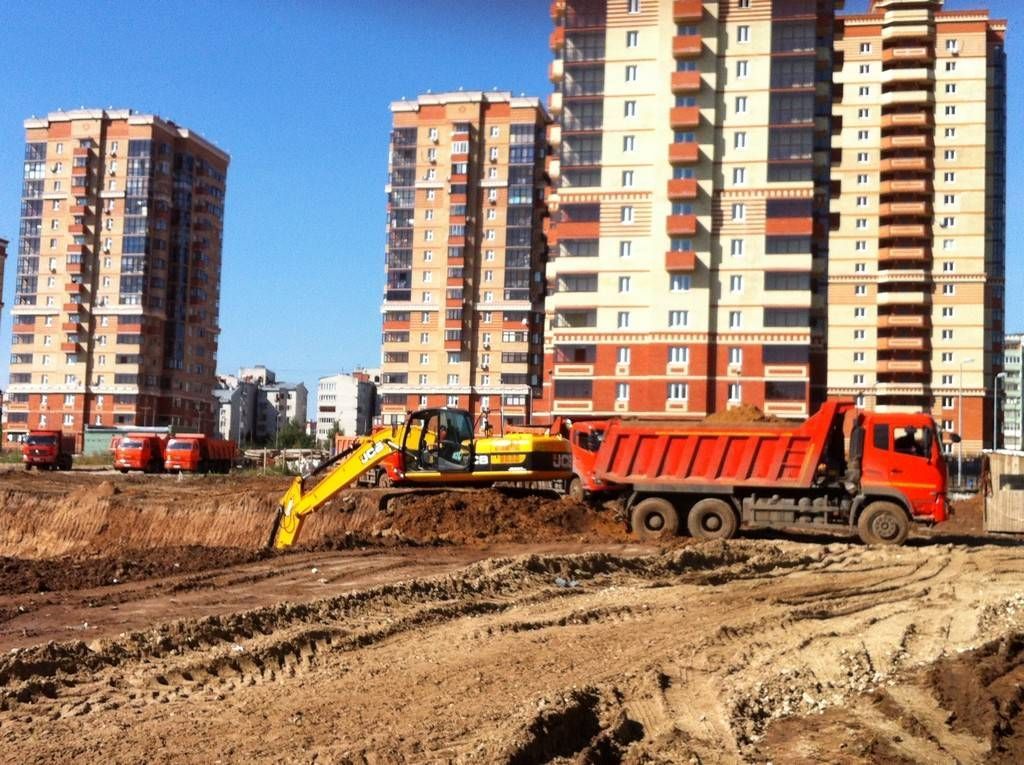
At the stage of drafting the project, it is necessary to calculate the volume of the pit, on which the practical scope of work for excavation, backfilling and removal of excess soil depends.
Differences in the composition of the rocks lying on the site lead to the fact that for the same foundations, the volumes to be taken out will differ due to the slope angle.
The calculation procedure is mandatory. If this moment is not reflected in the project for the construction of a private house, it is carried out independently before digging the foundation pit.
 The volume of the pit may depend on the features of the relief
Excavation is necessary for the construction of most industrial and civil structures. The way in which the calculation is made for a pit, trench or embankment is chosen individually in each case. It depends on the following factors:
- scale of work;
- purpose of the object (foundations of buildings, supports, laying of technological communications, arrangement of wells, open drainage systems);
- features of the relief of the construction site;
- method of excavation and removal of land (manual, mechanized), which will determine the need for arranging additional drives to the working area;
- site building density.
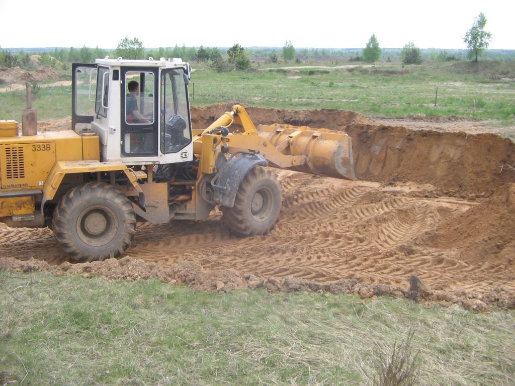
The scope of work on the development of soils is divided into those related to the planning of the site (cutting off the top layer of soil) and those related to the construction of pits. Some of them can be done with a bulldozer, stripping is done manually.
Accurate
 As close as possible to reality, the calculation of the volume of soil involves the following surveys (on the ground, office work):
- Definition of the calculation contour. With the help of topographic survey, characteristic points and elevations of the soil, the lower underlying surface of the excavation, accompanying cuts, embankments, drops, and ridges are determined.
- Subsequent cameral processing establishes additional (intermediate) points necessary for the correct determination of all values (contour, volumes, area of zero work). An assessment of the geological indicators of this area is being made.
- Drawing up a technical report indicating the conditions, grounds, results, actual and permissible errors.
A report with data calculated by a specialized organization will also be the rationale for determining the cost of work.
Independent
Determining the volume of earthworks when constructing a pit with slopes and trenches is not difficult after measurements have been taken (the length of the straight segments of the perimeter, the depth at the corresponding points).
In cases where the recess is a figure of complex shape, it is divided into simple geometric bodies (prisms with a triangle, rectangle, pentagon at the base). Summing up all the results gives the desired value of the excavation volume in the pit.
Knowing the area of the pit and all the heights in its constituent figures, it is convenient to use the service " online calculator". An example can be seen in this figure:
![]()
 By entering the appropriate values in the fields on the indicated variants of geometric bodies, a result is obtained, the accuracy of which depends on the selected calculation contour.
In relatively simple calculations, where the value of the possible error is not large, a formula is used that corresponds to the approximate size of the earthwork:

On sites with difficult terrain total length the trench is divided into fragments with the same slope, the volume of which is added to the total value.
slope requirements
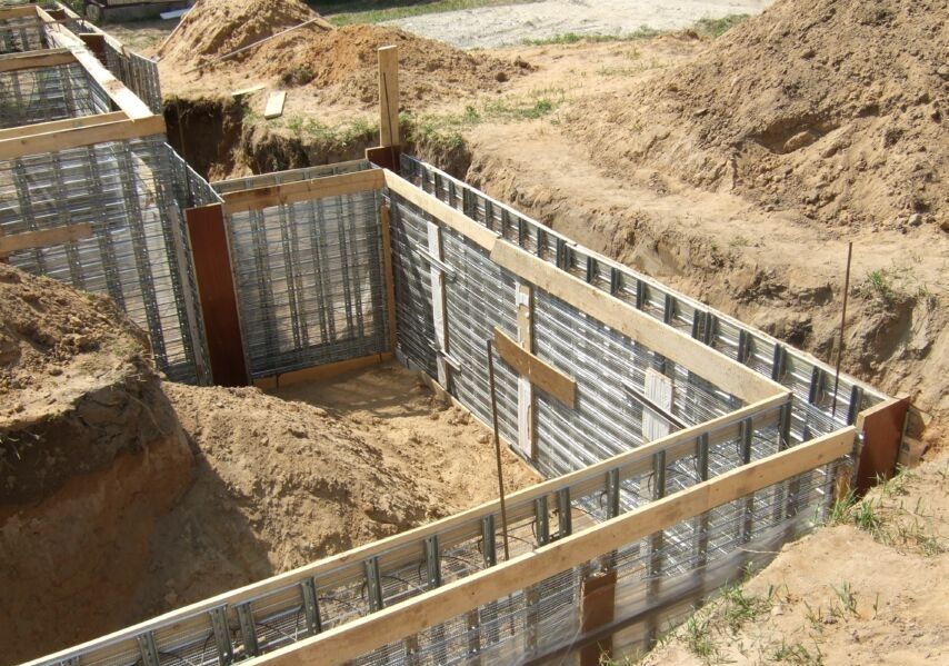 Slopes should not crumble and should be safe for workers
 The answer, what steepness should have slopes near an earthen structure, is contained in building codes. Deviation from the set standards causes not only an increase in the amount of work in case of wall collapse, but also the risk of injury to the worker.
The main determining parameters are the density of the soil forming the side surface and the depth of the excavation:
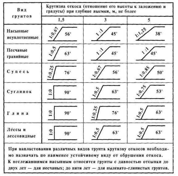
A related factor is the length of the pit - with large straight sections, collapses of the edge of the vertical side can also occur. At short intervals, round wells have a lower probability of this.
Additional points
In practice, when performing work on the construction of pits, there are specific operations that must be taken into account. For more information on how to calculate the volume of a pit in a special program, see this video:
 They are the following circumstances:
- digging a hole with a single-bucket excavator includes allowable shortfalls in soil, which are eliminated with a shovel;
- the trench for laying pipes is manually equipped with pits at the joints;
- for increase bearing capacity pipes by 30 - 40% increase the area of \u200b\u200bsupporting it on the base by sampling in the underlying surface of the furrow along the pipe Ø with a coverage angle of 120 °;
- the size of the backfill is determined by the difference between the volumes of the excavation and the underground part of the building.
It is possible to minimize the amount of exported or imported soil to complete all earthworks on the site, if at the design stage it is possible to calculate zero level, which will provide a balance between the volumes of excavation and backfilling.
SP 48.13330.2011 Organization of construction; SP 50.101.2004 Design and installation of bases and foundations for buildings and structures; STO NOSTROY 2.3.18.2011 Strengthening of soils by injection methods in constructionAlso watching:
Calculation of the volume of earthworks in the development of the pit and trenches online; Books and textbooks on construction
1. General Provisions
Purpose and types of earthworks
The volume of earthworks is very large, it is available during the construction of any building and structure. Earthworks account for 10% of the total labor intensity in construction.
The following main types of earthworks are distinguished:
- layout of the site;
- pits and trenches;
- roadbeds;
- dams;
- dams;
- channels, etc.
Earthworks are divided into:
- permanent;
- temporary.
Constants include pits, trenches, embankments, excavations.
Requirements for permanent earthworks:
- must be durable, i.e. resist temporary and permanent loads;
- sustainable;
- it is good to resist atmospheric influences;
- good resistance to erosive actions;
- Must be infallible.
Temporary earthworks are carried out for subsequent construction and installation works. These are trenches, pits, lintels, etc.
Basic building properties and soil classification
The soil is called the rocks occurring in the upper layers of the earth's crust. These include: vegetable soil, sand, sandy loam, gravel, clay, loess-like loam, peat, various rocky soils and quicksand.
According to the size of mineral particles and their interconnection, the following soils are distinguished :
Connected - clay;
Incoherent - sandy and loose (in a dry state), coarse-grained non-cemented soils containing more than 50% (by weight) of fragments of crystalline rocks larger than 2 mm;
Rocky - igneous, metamorphic and sedimentary rocks with a rigid connection between the grains.
The main properties of soils that affect the production technology, labor intensity and cost of earthworks include:
- bulk mass;
- humidity;
- blurring
- clutch;
- looseness;
- angle of repose;
Volumetric mass is the mass of 1 m3 of soil in its natural state in a dense body.
The bulk density of sandy and clay soils is 1.5 - 2 t/m3, rocky soils are not loosened up to 3 t/m3.
Humidity - the degree of saturation of the soil pores with water

g b - g c - mass of soil before and after drying.
At humidity up to 5% - soils are called dry.
With a moisture content of 5 to 15%, soils are called low-moisture.
At humidity from 15 to 30% - soils are called wet.
With a moisture content of more than 30%, the soils are called wet.
Cohesion - the initial resistance of the soil to shear.
Soil adhesion force:
- sandy soils 0.03 - 0.05 MP
- clay soils 0.05 - 0.3 MP
- semi-rocky soils 0.3 - 4 MPa
- rocky more than 4 MPa.
In frozen soils, the adhesion force is much greater.
Looseness- this is the ability of the soil to increase in volume during development, due to the loss of communication between the particles. The increase in soil volume is characterized by the coefficient of loosening K p. After compaction of the loosened soil is called the residual loosening K op.
|
soils |
Initial looseness K r |
Residual looseness K or |
|
sandy soils |
1,08 - 1,17 |
1,01 - 1,025 |
|
loams |
1,14 - 1,28 |
1,015 - 1,05 |
|
Clay |
1,24 - 1,30 |
1,04 - 1,09 |
|
Mergeli |
1,30 - 1,45 |
1,10 - 1,20 |
|
rocky |
1,45 - 1,50 |
1,20 - 1,30 |
Angle of repose characterized by the physical properties of the soil. The value of the angle of repose depends on the angle of internal friction, the adhesion force and the pressure of the overlying layers. In the absence of adhesion forces, the limiting angle of repose is equal to the angle of internal friction. The steepness of the slope depends on the angle of repose. The steepness of the slopes of cuts and embankments is characterized by the ratio of height to foundation  m - slope factor.
Angles of repose of soils and the ratio of slope height to foundation
|
soils |
The value of the angles of repose and the ratio of the height of the slope to its inception at different soil moisture |
|||||
|
Dry |
Wet |
Wet |
||||
|
Angle to degrees |
Height to lay ratio |
Angle to degrees |
Height to lay ratio |
Angle to degrees |
Height to lay ratio |
|
|
Clay |
45 |
1: 1 |
35 |
1: 1,5 |
15 |
1: 3,75 |
|
Loam medium |
50 |
1: 0,75 |
40 |
1: 1,25 |
30 |
1: 1,75 |
|
Light loam |
40 |
1: 1,25 |
30 |
1: 1,75 |
20 |
1: 2,75 |
|
Fine-grained sand |
25 |
1: 2,25 |
30 |
1: 1,75 |
20 |
1: 2,75 |
|
Medium sand |
28 |
1: 2 |
35 |
1: 1,5 |
25 |
1: 2,25 |
|
Sand coarse-grained |
30 |
1: 1,75 |
32 |
1: 1,6 |
27 |
1: 2 |
|
plant soil |
40 |
1: 1,25 |
35 |
1: 1,5 |
25 |
1: 2,25 |
|
bulk soil |
35 |
1: 1,5 |
45 |
1: 1 |
27 |
1: 2 |
|
Gravel |
40 |
1: 1,25 |
40 |
1: 1,25 |
35 |
1: 1,5 |
|
Pebble |
35 |
1: 1,5 |
45 |
1: 1 |
25 |
1: 2,25 |
Soil erosion - entrainment of particles by flowing water. For fine sands, the highest water velocity should not exceed 0.5-0.6 m/s, for coarse sands 1-2 m/s, for clay soils 1.5 m/s.
According to production standards, all soils are grouped and classified according to the degree of difficulty of development by various earthmoving machines and manually.:
- for single-bucket excavators - 6 groups;
- for multi-bucket excavators - 2 groups;
- for manual development - 7 groups, etc.
Calculation of volumes of earthworks
In the practice of construction, it is necessary mainly to calculate the volume of work for vertical layout sites, the volume of pits and the volume of linear structures (trench, subgrades, embankments, etc.).
The volume is calculated in the working drawings and specified in the project for the production of works.
Excavation projects should include an excavation cartogram, a bill of fill and cut volumes, and a general soil balance sheet.
The project must have the volume and direction of movement of soil masses in the form of a sheet or cartogram.
The technology of development, soil transportation, backfilling and compaction should be thought out.
The project should include a calendar schedule for earthworks, human, material resources and the choice of a set of machines.
When calculating the volume of excavation of pits, trenches, excavations of embankments, all known geometry formulas are used.
With complex forms of cuts and embankments, they are divided into a number of simpler geometric bodies, which are then summarized.
Determination of the volumes of soil masses in the development of pits
In most cases, the pit is a truncated rectangular pyramid, the volume of which is determined by the formula
:


The entrance trench is determined by the formula:

Determination of the volumes of soil masses in the construction of linear structures
The volume of earthworks for linear structures of embankment, excavation, trench can be calculated by the formula:


With a slope not exceeding 0.1, you can use the formula F.F. Murzo:

m - slope factor.
If the slope exceeds 0.1, then use the formula


Calculation of volume on curves (Thulden's formula):
 r- radius of curves
α
- central corner turning
Calculation of earthwork volumes in site planning
It is most expedient to design the layout of the site so that a zero balance is observed. earthen masses, i.e. redistribution of earth masses on the site itself, without the import or export of soil.
The volume of earthworks is determined on the basis of the cartogram.
The site plan is divided into squares with a side of 10 to 50 m, depending on the terrain. With a more complex terrain, the squares are divided into triangles.
The average mark of the surface of the site, when broken down into squares, is determined by the formula:

ΣH 1- the sum of marks of points where there is one vertex of the square;
ΣH2- the sum of marks of points where there are two vertices of the square;
ΣH4- the sum of marks of points where there are four vertices of the square;
n- The number of squares.
When broken down into triangles, according to the formula:
ΣH 1- the sum of marks of points where there is one vertex of the triangle;
ΣH2- the sum of the marks of the points where there are two vertices of the triangle;
ΣH 3- the sum of marks of points where there are three vertices of the triangle;
ΣH 6- the sum of the marks of the points where there are six vertices of the triangle;
n- the number of squares.
As a rule, additional earthworks in the form of embankments and excavations are always erected on the planned site.
To ensure a zero balance of earthworks, the construction of these structures is taken into account by introducing an amendment to the average planning mark and the coefficient of residual loosening of the soil.
Distribution of earth masses on the site.
After the volumes of earthworks are calculated, they begin to distribute the earth masses. From which area where to transport the land.
Before this, it is necessary to draw up a balance of earthworks. How much excavation will be, how much embankment.
When distributing earth masses, it is necessary to take into account the profile volume of earthworks and the working volume of earthworks. The worker is larger, it takes into account the slopes.
Distribution of earth masses in a linear structure
Taken into account:
- longitudinal transportation of soil;
- transverse transportation of soil.
Which way to take can be decided using the inequality:
C vk + C nr ≤ C vn
Свк - the cost of developing excavation and laying the soil in the cavalier;
С нр - the cost of dumping into the embankment from the reserve;
C vn - the cost of developing the soil and filling it into an embankment.
The correct calculation of the cost of transportation for certain distances is important.
To correctly determine the length of the movement of the soil, the centers of gravity of the embankment and excavation are taken and this will be the average distance for transportation.
General information about machines designed for earthworks
Soils are developed by mechanical, hydromechanical, explosive, combined and other special methods.
mechanical way- 80-85% is done in this way, by separating the soil by cutting with the help of earth-moving machines (single-bucket and multi-bucket excavators) working for transport or dumping, or earth-moving machines: bulldozers, scrapers, graders, graders-elevators and ditchers.
Hydromechanical method- hydraulic monitors - they erode the soil, transport and stack or suck the soil from the bottom of the reservoir with dredgers.
Explosive way- based on the use of the force of the blast wave of various explosives placed in specially arranged wells, is one of the powerful means of mechanizing labor-intensive and hard work.
Combined method- combines mechanical with hydromechanical or mechanical with explosive.
Special Ways- destroy the soil with ultrasound, high-frequency current, thermal installations, etc.
For preparatory work, brush cutters, rooters, rippers, etc. are used.
The soil is transported by dump trucks, trailer, conveyors, railway. transport and hydraulic method.
All kinds of rollers, rammers and vibration machines are used to compact the soil.
Single bucket excavator- self-propelled earth-moving machine of cyclic action; attachments: front shovel, backhoe, dragline, grapple, plow and backfiller.
In addition, replaceable equipment is used: a crane, a pile driver, a tamper plate, a stump remover, a concrete breaker, etc.
With a bucket capacity of 0.25; 0.3; 0.4; 0.5; 0.65; one; 1.25; 2.5; 3; 4.5 m 3 - used in construction, and 40; fifty; 100; 140 m 3 is used in overburden work.
The maximum at the construction site is usually 2.5 m 3 .
Bucket excavator- self-propelled earth-moving machine of continuous action. There are chain and rotary.
Bulldozer- the knife blade is hung to the tractor. Tractor power 55 - 440 kW (from 75 to 60 hp).
Bulldozers are used for digging, moving and leveling the soil, as well as cleaning it up in pits.
Scrapers- consist of a bucket and a running gear on a pneumatic duct. There are trailed scrapers with a bucket capacity of 2.25 - 15 m 3, self-propelled 4.5 - 60 m 3. Working speed of movement is 10 - 35 km/h.
They are used for layer-by-layer digging, transportation and backfilling with soil layers. (The cheapest in earthworks).
road graders- self-propelled machine on the frame of which there is a blade with a cutting knife. Designed for planning and profiling work with soil.
Elevator graders- equipped with a disc plow. They are used for layer-by-layer cutting of soil and moving it to a dump or vehicles.
New service - Construction Calculators online
2. The device of cuts and embankments
Pit device
A pit is a recess intended for the construction of a part of a building or structure located below the surface of the earth, for the construction of foundations.
Pit pits come with vertical walls, with fasteners and with slopes.
According to SNiP, it is allowed to dig pits with vertical walls without fastenings in soils of natural moisture with an undisturbed structure, in the absence of groundwater and the depth of pits in bulk, sandy and gravelly soils is not more than 1 m; in sandy and loamy 1.25 m; in clay 1.5 m and extra-dense 2 m.
Mounts are:

strut anchor sheet pile
But it is better to carry out a pit with slopes. The highest allowable steepness of slopes of pits in soils of natural moisture and in the absence of groundwater is taken for excavations
Depth up to 1.5 m from 1: 0.25 to 1: 0;
depth 1.3 - 3 m from 1: 1 to 1: 0.25;
depth 3 - 5 m from 1: 1.25 to 1: 1.5.
For deeper pits, slopes are calculated.
Pit development includes the following work steps:
- development of soil with unloading on the edge or loading into vehicles;
- soil transportation;
- layout of the bottom of the pit;
- backfilling trimmed and sealed.
Digging a pit is the leading process. The pits are developed with a single-bucket excavator, scraper, bulldozer and hydromechanical method.
Single bucket excavator used:
- in the construction of housing 0.3 - 1 m 3;
- in industrial construction 0.5 - 2.5 m 3 sometimes 4 m 3.
trenching
Trenches are temporary excavations intended for laying strip foundations in them or installing pipelines and cables.
There are 3 types of trenches : vertical walls, sloped, and mixed trenches:

Most trenches with vertical walls require fastening, which means additional consumption of materials, additional labor costs
Without fastening, you can dig from 1 to 2 m, depending on the density of the soil. But they recommend immediately laying pipelines or building a foundation.
In viscous soils, bucket-wheel excavators dig up to 3 meters, laying pipelines (gas pipelines, oil pipelines, etc.), fastenings are performed where people descend.
When constructing trenches with slopes, the greatest steepness is taken in accordance with the angle of repose and weather conditions.
Mixed-type trenches are arranged with great depth and the presence of groundwater, the level of which is higher than the bottom of the trench.
Trench fastenings are:
Horizontal or vertical;
- with gaps or solid;
- Inventory or non-inventory.
Inventory fences consist of collapsible frames and inventory boards, inventory spacers.
For the development of trenches, single-bucket excavators are used: a backhoe or a dragline with a bucket capacity of 0.3 - 1 m 3.
The backhoe can be developed with vertical walls. Dragline with slopes and in the presence of groundwater.
If the trenches are not deep, then the dump is organized next to the trench (lateral or end movement).
If the trench is deep, then the blade is on both sides and the excavator moves in a zigzag.
A bucket-wheel excavator is used in the development of trenches for laying pipelines.
Operational changeable productivity of bucket-wheel excavator:

c- the duration of the shift;
n 1
- the number of unloaded buckets per minute depends on the speed of movement and the distance between them;
k1- excavator utilization rate;
k3- bucket load factor;
g- bucket capacity.
If the soil in the trench is moved, then sand or small gravel is laid and it is rammed (but not the soil). When developing trenches for foundations, the soil from under the excavator is usually taken away by dump trucks.
Sometimes in very cramped conditions or when pipelines pass through a road or other obstacles, adits are dug or a puncture is performed (trenchless laying).
The fastening of the trenches is dismantled from the bottom up, but they can also be left (for example, in quicksand).
Backfilling of trenches is carried out after geodetic survey of laid pipelines or other communications.
Backfilling is carried out in two stages: first, the pipe is sprinkled with 0.2 m sand or fine gravel, and then everything else with layer-by-layer compaction.
The device of underwater trenches
Underwater trenches are arranged for laying siphons. A trench is always developed with slopes, the steepness of which is taken for sandy soils from 1:1.5 to 1:3, for sandy loam and loam 1:1 - 1:2, for clays 1:0.5 - 1:1.
With the width of the development of trenches, the speed of the river flow is taken into account (for small rivers, the channel is diverted).
The development of underwater trenches, depending on local conditions, is carried out by an excavator, a rope-scraper installation, dredgers, and hydraulic monitors.
In some cases, trenches are developed manually.
Ground bed device
The subgrade is the base of the upper structure of automobile and railways, consists of embankments and recesses.
The steepness of the slope is taken depending on the type of soil and the height of the embankment.
For non-cohesive soils with an embankment height of up to 6 m, a slope of 1: 1.5 is recommended.
Embankments from 6 m and above should have slopes of a broken profile, more gentle in the lower part.
The process of arranging the subgrade consists of 2 works : preparatory and main.
preparatory- cleaning of the route and breakdown of the canvas.
Main- development, movement, planning and compaction of soil.
On each section of the subgrade, the soil is developed by machines of one or more types, which are selected taking into account the conditions of their use and ensuring the highest productivity.
Bulldozers used in the construction of excavations up to 2 m and embankments with a height of 1 - 1.5 m with a travel length of 80 - 100 m.
Scrapers are used for longitudinal movement of soil from excavations to an embankment at a distance of movement of more than 100 m, as well as when embankments are arranged from lateral reserves.
Elevator graders- it is advisable to use in the construction of low (up to 1 meter) embankments from reserves in flat terrain. The front of the work of each machine should be within 1.2 - 3 km, the length of the grip should be at least 400 m.
Graders and Motor Graders are mainly intended for planning and profiled works, they can also be used as main machines in the construction of subgrades with an embankment height of up to 0.75 m.
Excavators- a straight shovel or dragline is used where the concentrated masses of soil are not less than a normal face in height.
Means of hydromechanization apply if there are natural reservoirs and sources of electricity in the area of work on the subgrade.
Fixing slopes of permanent earthworks and banks
During the construction of subgrade, canals, water supply and sewerage and other structures, it is necessary to carry out work on fixing slopes and banks.
The soil of the slopes and banks is fixed with organic binders (bitumen), grass sowing, protective clothing in the form of turf, as well as brushwood, stone, reinforced concrete slabs and special protective structures.
A more durable fastening is paving or riprap in wattle cages ranging in size from 1 x 1 to 1.2 x 1.2 m.
3. Auxiliary work in the production of earthworks
Drainage
Excavations in aquifers are developed using open drainage or artificial dewatering of the groundwater level.
Drainage is used when there is a small flow of water.
Disadvantages of drainage:
- Blurs the walls of recesses;
- The influx of water makes it difficult to excavate;
- The bottom of the pit is not always dry.
Therefore, they arrange an artificial lowering of the groundwater level.
Dewatering
The lowering of the groundwater level is carried out : with the use of light wellpoints, providing a single-tier lowering of the groundwater level to 4 - 5 m, and with a two-tier one by 7 - 9 m; ejector wellpoints, allowing a single-tier lowering of the groundwater level to 15 - 20 m; and tubular wells with deep pumps.
Lightweight wellpoints consist of a set of wellpoints, a suction manifold and pumps.
Pipes are immersed by hydraulic method or drilling. For deep pits, there can be 2 and 3 tiers.
For trenches, it is possible to arrange from one side.
Wellpoints with an ejector device are used to lower the groundwater level in one tier to a depth of 15–20 m.
Deep tubular wells carry out a single-tier lowering of groundwater to a depth of 60 m or more.
Submersible pumps are installed in pre-drilled filtered wells (casing pipes) d 200 - 400 mm.
Artesian pumps are also used.
Artificial fencing of excavations from groundwater
Soil excavations during penetration of layers with a significant influx of water can be carried out under the protection of an ice waterproof wall of frozen soil or with the help of thixotropic impervious screens.
Artificial freezing of soils is used in the development of recesses in quicksand in order to create a temporary waterproof ice wall.
Thixotropic screens are made from bentonite clays or from simple clays mixed with cement 1:2.
Clays absorb water up to 7 times their own weight and, after saturation with water, thicken, acquiring a water-repellent quality.
4. Features of earthworks in winter conditions
General information
In winter, the soil structure changes: mechanical strength as well as resistivity cutting and digging increases sharply (several times).
Therefore, earthworks are very different from summer ones. But sometimes winter conditions favor earthworks. For example, in swamps, when developing silty soils, soils saturated with water.
Due to groundwater in spring, the soil thaws from below. Therefore, at the time of thawing, groundwater rises.
The first ice crystals in groundwater appear at t = -0.1°C. Ground freezing begins at -6°C and below.
In loose soils, sand, sandy loam, water freezes at t = (- 2°С - 5°С), in clay soils at t = (- 7°С - 10°С).
The temperature inside the soil is distributed depending on the depth.
|
ground temperature, in °С |
Depth, in m |
|
|
Without snow |
Snow 35 cm |
|
|
5 |
0,5 |
0,5 |
|
4 |
0,75 |
0,6 |
|
2 |
1,0 |
0,75 |
|
1 |
1,25 |
1,15 |
|
0,5 |
1,85 |
1,75 |
|
0,0 |
2,25 |
2,0 |
The depth of soil freezing depends on:
humidity - the higher the humidity, the more depth. At a humidity of 30 - 40% leads to heaving of the soil;
- groundwater level - the closer the groundwater to the surface, the less freezing;
- the nature of winter and the time of snowfall. The sharper the fluctuations of the outside air, the greater the depth of freezing.
The depth of freezing can be determined by the following formula (the ground is not covered with snow):

H- freezing depth
k- coefficient taking into account the characteristics of the soil:
- clay - 1;
- loam - 1.06;
- sandy loam - 1.08;
- sand - 1.12.

z- the number of days of winter before the settlement day.
t- the average outdoor temperature for the period from the beginning of winter to the settlement day.
In addition, the freezing depth can be determined from various graphs and tables. In general, the depth of freezing is determined in kind.
Protecting the soil from freezing
In general, it is difficult to protect the soil from freezing.
The simplest is loosening: harrowing with a depth of 0.15 - 0.2 m, plowing 0.25 - 0.35 m, deep loosening with an excavator up to 1.5 m.
Provide drainage of autumn waters.
They arrange snow retention with a thickness of 0.5 - 1.0 m. For insulation, they cover with dry peat, foliage, slag (sawdust is not allowed).
Water-air coating with foam from surface-active substances (surfactants), arranged with the help of foam generators with a layer of 30 - 40 cm, reduces the freezing depth by 10 times.
But warming the soil is advisable only in the first half of winter.
Loosening frozen soil
When the soil freezes up to 0.1 m, it is developed without loosening.
Frozen soil is loosened by explosive or mechanically.
The explosive method of loosening is beneficial at a freezing depth of more than 0.8 m (the method is cheap).
The volume is divided into grips, holes are drilled, explosives are laid, blown up and developed in the usual way.
Mechanized loosening at a depth of 0.25 - 0.4 m with a ripper or an excavator with a bucket of 0.5 - 1 m 3.
If the freezing depth is 0.5 - 0.7 m and the volume is not large, free-fall hammers are used, which are in the form of a wedge or ball, concrete breakers based on a hydraulic excavator.
With a freezing depth of up to 1.3 m, it is better to use a diesel hammer with a wedge.
In addition, frozen soil can be cut into blocks with a bar, which are then removed.
A small amount of work is carried out with jackhammers.
Thawing of frozen ground
This method is used for small amounts of work, usually in cramped conditions.
The soil can be thawed:
- hot water;
- ferry;
- electric current;
- fire method;
- chemically (quicklime).
hot water or steam is fed through needles placed in pre-drilled boreholes.
electric current- electric needles, electric furnaces, heating elements, coaxial heaters, horizontal or driving electrodes.
fire method- burning any fuel (peat, coal, firewood, wood chips, diesel fuel, etc.) under a metal box or pipe.
Excavation, backfilling and embankment
In winter, the soil is developed in the usual way.
Excavation is carried out consistently, quickly and the foundations are laid while the soil is warm.
Shallow trenches (up to 1.5 m deep) for foundations are insulated.
backfilling is carried out in compliance with the following requirements: when backfilling the sinuses of pits and trenches, frozen clods should not exceed 15% of the backfill volume, inside the building they are covered only with thawed soil.
Pipelines of 0.5 m are covered with thawed soil.
Above, you can fill it with frozen soil that does not contain clods larger than 5-10 cm.
Erection of subgrade embankments in winter conditions: when constructing a road embankment, up to 20% of frozen soil is allowed, and a railway embankment - up to 30%.
Clay soils in the embankment should be no more than 4.5 m.
The top layer of the embankment is thawed soil 1 m thick.
When planning the site, up to 60% of frozen soil is allowed.
The foundation for foundations can be rented frozen, but not in heaving soils.
5. Organization of a complex-mechanized process of erection of earthworks
With complex mechanization, all earthwork processes are carried out mechanized: loosening, excavation, soil transportation, leveling, compaction.
The leading machine is selected, which should be used to the fullest.
The rest of the set of cars is selected for it.
The cost of 1 m 3 of processed soil is determined and the set of machines is compared with another set.
C with- specific costs per 1 m 3
From 0- total cost of earthworks
V- overall volume
With m.sm.- the cost of a machine shift in rubles.
T- the duration of the machine at this facility
C d- additional costs associated with the organization of earthworks, rubles (road construction, road maintenance, etc.)
W- Wages of workers not included in the cost of machines.
6. Quality control of earthworks and their acceptance
It is necessary to systematically check the performance of project documentation and the requirements of SNiP 3.02.01-87 "Earth structures, bases and foundations".
It is necessary to keep a work log, which reflects the properties of the soil (plasticity, moisture content, viscosity, etc.).
After the excavation is completed, a tripartite act (customer, contractor, geologist or designer) is drawn up on the compliance of the supporting base with the project to enable further work to be carried out.
When handing over earthworks, the contractor must submit to the commission executive drawings, in which all changes, deviations from the project, acts of hidden work, acts of testing the soil, acts of geodetic surveys are applied.
The necessary instructions on how to determine the amount of earthwork are contained in SNiPs. For more detailed explanations, see the published different years manuals and guides. If your work does not require high counting accuracy, you can choose a simpler technique.
In practice, there are different ways determining the amount of excavation, using which you will receive one or another degree of accuracy. In the case of large-scale projects, deviations of the result from the plan can be very significant, and therefore this stage plays a special role. The calculation of the volume of earthworks helps to correctly determine the required labor and technical resources, draw up a calendar plan and approve the estimated cost. Moreover, clarifications on the scope of work in the documentation can be made not only at the design stage, but also later.
Photo source: volvoce.ru
If earthworks imply a result in the form of a regular geometric shape, then to determine the volume, it is enough to use a formula from among the commonly used ones. With the complication of the relief, the methods of counting become more laborious. In this case, a suitable formula can be found in reference books.
Of the variety of forms of earthworks, three main ones are distinguished: a pit, a trench (another name is a linear-extended structure), and a vertical layout of the site. In the first case, to determine the volume, preference is given to the method of transverse profiles (in the case of a polygonal shape with parallel bases, you can use the Simpson formula), in the second, the calculation is in most cases carried out according to longitudinal and transverse profiles.
Schemes for determining the volume of earthworks (rectangular, polygonal, round pits, trenches with slopes, embankment)

In the event that the contractor is dealing with complex shape, to determine the total volume, a breakdown is performed into several simpler figures, followed by summing up the values obtained for each of them. Individual irregularities may not be taken into account as they do not significantly affect the amount of work to be done. When calculating the volume of an extended earthen structure, it is divided by vertical planes into several prismatoids at the fracture points of the longitudinal profile. To determine the volume of each part, it is necessary to know the dimensions of the sides of the cross sections and the distance between them. Vertical planning on the territory of a large area involves counting by 3-sided or 4-sided prisms, the sides of which are taken 10-100 m long.
One of the frequently encountered values for determining the volume of earthworks is the steepness of the slopes. The literature gives approximate steepness values, depending on the depth of excavation and the strength of the soil. Thus, the angle of repose of a pit up to 1.5 m deep in the sand is 63 degrees, and the ratio of the height of the slope to its inception is 1:0.5. Having the value of this value, as well as the dimensions of the lower part of the pit and its depth, you can easily calculate the length and width of the earthen structure from above and the volume of soil to be excavated.
If you are digging a pit deeper than 5 m, take care in advance of the installation of intermediate berms no narrower than 2.5 m. A few more recommendations:
- when erecting a strip foundation, 0.2 m is added to the width of its sole on each side (for the construction of a cushion of sand or concrete);
- if the purpose of the work is a trench with fastening, 0.1-0.2 m should be added to its width (the deeper the pit, the greater the value).
An additional distance should be provided for in other cases, for example, in the manufacture of vertical waterproofing of foundations.
There is a specificity in determining the scope of work when using special equipment. So, the trench cannot be narrower than the cutting edge of the earth-moving machine bucket plus 0.1-0.15 m (depending on the type of soil). And in order to exclude a violation of the natural structure of the soil, it is customary to "underdraw" with a bucket from the bottom of 5-20 cm.
 Photo source: cat.com
In addition to the scope of the main work, it is customary to make calculations for additional earthworks, such as exits from the pit, widening for a turnaround of vehicles, and other elements, without which the project is impossible to implement. From the total volume of the pit, the volume of work on cutting off the upper fertile layer is also distinguished.
Another point that should be taken into account is that when determining the volume of earthworks, the calculation is carried out at the density of natural occurrence ("in a dense body"). In this case, the working height of the embankment should be set higher than the design one, since subsequently the soil may settle. Example: the initial increase in the volume of sandy soil after development is 10-15%, the residual loosening of the soil (after compaction by precipitation, transport, etc.) is 2-5%.
The calculation of the volume of earthworks is carried out in the design process and during the execution of works.
An earthen structure - a cut or an embankment - can be represented as a geometric body, the volume of which is calculated according to the known rules of geometry. Formulas for counting characteristic earthworks are given in earthworks reference books. When calculating the volume of an earthen structure of complex configuration, they resort to dividing it into simple geometric shapes and summing up their volumes, or use approximate calculation methods.
In the practice of industrial and civil construction, it is mainly necessary to calculate the volumes of linearly extended structures (trenches), pits and work on the vertical planning of sites. To determine the volume of each type of earthwork, there are various methods and calculation formulas. The feasibility of the calculation method is selected in each specific case, taking into account the terrain, size, configuration and other features of structures, methods of work, and also based on the required accuracy of calculations.
In the production and calculation of the volume of work, surface marks have the following names:
- red - design mark, under which it is necessary to plan a site or earthwork;
- black - the actual mark of the earth's surface before the start of work;
- working - this is the difference between the red mark (design) and the mark of the earth's surface, working marks determine the depth of the excavation or embankment.
The main source documents for calculating the volume of earthworks are the longitudinal and transverse profiles of structures, the location of individual foundations and buildings on a plan with contour lines.
When calculating the volume of earthworks during the breakthrough of trenches and pits, it is necessary to correctly determine their dimensions. The calculation of volumes is reduced to determining the volumes of various geometric shapes that determine the shape of a particular earthen structure. In this case, the assumption is made that the volume of the earth is limited by planes and individual irregularities of the actual surface of the soil do not significantly affect the calculated volume.
The volume of extended earthworks is calculated by the approximate method of transverse profiles, based on the division of the structure at the characteristic fracture points of the longitudinal profile or on pickets by vertical planes into prismatoids. From the cross-sectional area and the distance between them, the partial volumes of each prismatoid are determined, which are then summed up. To facilitate the calculations, there are manuals, reference books, tables, nomograms.
The volume of a pit with rectangular bases, having slopes on all four sides, is determined, for example, by the transformed formula:
V = (H/6) (ab + cd + (a + c)(b + d))
where H is the depth of the pit; a and b - respectively, the width and length of the pit along the bottom; c and d - the same, on top.
In the production of calculations of the volume of earthworks during the excavation of trenches and pits, it is necessary to correctly determine their sizes, depending on the conditions of the work. When developing trenches for strip foundations the width of the bottom of the trench is taken equal to the width of the base of the foundation plus 0.2 m on each side for sand or concrete preparation. If the trench is developed with fastening, then for its installation it is necessary to increase the bottom width by 0.1 m at a depth of up to 2 m and by 0.2 m at a depth of up to 3 m. at a depth of up to 3 m with the addition of 0.2 m for each meter of depth over 3 m. If necessary, vertical waterproofing of foundations and basement walls should also be widened for ease of work.
The width of the trenches along the bottom for laying pipelines is determined depending on the size of the pipes and the way they are laid.
When excavating soil with earthmoving machines, the smallest width of trenches along the bottom should correspond to the width of the cutting edge of the working body of the machine plus 0.15 m in sandy and sandy loamy soils, 0.1 m in clay and loamy soils.
The working depth of the foundation pit is determined by the difference between the black and red marks. To take into account the nature of the terrain in practical calculations, it is enough to take an average black mark equal to the arithmetic mean of several marks.
In order to prevent violation of the natural structure of the soil during the operation of the excavator, a shortage of soil is provided in the range from 5 to 20 cm. The working height of the embankment of an extended structure is set more than the design value, taking into account the subsequent settlement of the soil.
The source document for calculating the volume of earthworks in vertical planning is a cartogram of earth masses, which is a site plan on which the relief is depicted by contour lines, with a grid of squares and indicating black, red and working marks of the tops of the squares, as well as with the image of the line of zero work. The cartogram is compiled during the design master plan geodetic service of a design and survey organization, however, before starting planning work, production workers often have to clarify it.
The average elevation of the layout can be set in accordance with the needs of the construction, but most often it is determined from the zero balance condition, i.e., the equality of the excavation and embankment earth masses within the planned site.
Calculation of the volume of earthworks for vertical planning on large areas can be produced on trihedral or tetrahedral prisms. To do this, the planned area with horizontal lines drawn on it is divided into a number of squares, which are then divided by diagonals into right-angled triangles. The side of the square, depending on the terrain and the accuracy of the calculation, is taken for a rugged terrain of 10-50 m, and for a calm terrain - up to 100 m. Working marks with a (+) sign indicate the need to cut the soil, i.e., an excavation device, and marks with a (-) sign indicate the need for an embankment. Triangles with working marks of the same sign are called triangles of the same name, and triangles with different signs are called transitional.
The total volume of earthworks in the planning of sites is determined as the sum of all private volumes.