
Statement of volumes of earthworks how to calculate. Consolidated balance of earth masses
1.2 Soil distribution based on earth mass balance
Comparison of volumes earthworks on the device of excavations and embankments at the construction site is a balance of earth masses, which can be active if the volume of excavations exceeds the volume of embankments, and passive if the volume of excavations is less than the volume of embankments. In the first case, excess soil is removed from the construction site to dumps, in the second case, the soil missing for the construction of embankments is imported from outside.
Since the removal of soil from the site is undesirable, since it increases the time and cost of construction, one should strive to ensure that all soil from the excavations is placed without residue in the embankment, i.e. to maintain a zero balance on the site. To obtain such equality, it is necessary to determine the optimal level of the site layout, at which a zero balance of earth masses will be achieved.
The optimal layout mark, on both sides of which (top and bottom) there will be equal volumes of excavation and embankment when calculating volumes by squares (Fig. 2, a, b), is determined by the formula:
where H1, H2, H3, H4 - marks of the natural surface of the site at the vertices common for one, two, three and four squares, respectively, m; n is the number of squares within the site.
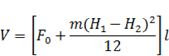
When planning the site of a complex of structures, the optimal level of planning must be adjusted taking into account the additional volumes of soil required for the installation of permanent structures, and the volumes of soil displaced by the underground parts of the structures and communications under construction. The correction to this mark can be determined by the formula:
![]()
where Vi is the additional volume of soil (accepted with a plus when there is a surplus, and with a minus when there is a lack of soil), m3; F - area of the planned site, m2.
After the end of the calculation, all volumes of earthworks are reduced to a special sheet, called the summary balance of earth masses and consisting of two parts: the left - the arrival of soil (P) and the right - soil consumption (P). When P>P, the balance is positive, i.e. active, at P<Р баланс отрицательный, т.е. пассивный, и при П=Р баланс нулевой. Определив баланс земляных масс, составляют схемы потоков перемещения грунта из выемок в насыпи или в резервы.
The volumes of embankments and excavations of significant length (roadbed, dams, dams, etc.) are calculated using the longitudinal and transverse profiles of the structure. At characteristic points of the longitudinal profile, places of change in the slope of the terrain or the red (design) line, the structure is divided by vertical planes into parts, within which geometric bodies are obtained - prismatoids. The height of the prismatoid is equal to the length of the section between the sections, and the bases are the profiles of the structure in the places of the sections. This method is also sometimes referred to as the cross profile method.
The total volume of a structure is defined as the sum of the volumes of the prismatoids.
With transverse slopes of the terrain not exceeding 0.1, the volume of the prismatoid (m3)
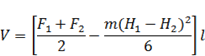
where F1, F2, F0 are the cross-sectional areas at the beginning, end and middle of the section, m2; H1 and H2 - working marks at the beginning and end of the section, m; m - slope coefficient; l - section length, m.
The calculation is more convenient to carry out in tabular form.
1.3 Volume of pits and trenches
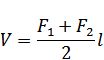
If a pit is being developed on a planned site or on terrain with a slope of not more than 0.01, its volume can be calculated as the volume of a truncated wedge (overturned obelisk):
![]()
where H is the average depth of the pit, m; F1 and F2 - respectively, the areas of the lower and upper foundations of the pit.
With a significant size of the pit located on a terrain with large slopes, its volume can be calculated using the formulas and.
1.4 Scope of work for vertical planning
The volumes of earthen masses moved during planning can be calculated using the method of cross-sections, quadrangular and triangular prisms. For calculations, the results of leveling by squares or the plan of the site in horizontal lines with a grid of squares with sides from 10 to 100 m, depending on the relief and size of the site, are used.
The method of cross-sections is used in calm terrain for tentative calculations and at the stage of preliminary design studies that do not require high accuracy of calculations. In characteristic sections of the terrain, cross profiles are drawn, spaced from each other by no more than 100 m. The area of \u200b\u200beach diameter and the volume of soil located between the cross sections are determined.
The method of quadrangular prisms is quite accurate, but is associated with a significant complexity of the calculation.
The triangular prism method used both at the design stage and in the production of works provides the necessary calculation accuracy for complex (rough) terrain.
It is most advisable to carry out vertical planning with a zero balance of earth masses, in which the volumes of excavation and embankment are equal, i.e. the soil is redistributed within the planned site.
Calculation of volumes by the method of quadrangular prisms or by the method of squares with a zero balance is carried out in the sequence shown below (Fig. 4).
The average mark of the layout - the mark of the horizontal plane, on both sides of which (top and bottom) there will be equal volumes of excavation and embankment, is determined by the formula
where H1, H2, H3, H4 are marks of the natural surface at the vertices common to one, two, three and four squares, respectively; n is the number of squares within the area under consideration.
To determine the position of the design planning plane, the elevation of the horizontal plane is adjusted taking into account the slopes necessary to ensure surface drainage from the site. Then the working elevations of the square vertices are calculated as the difference between the elevation of the design plane and the elevation of the natural relief. Working marks with a "+" sign indicate the need to cut the soil (excavation), with a "" sign - backfilling devices (embankment). On the site plan, the line of zero work is indicated - the line of transition from the excavation to the embankment.
According to the working marks in each square, the volume of a tetrahedral prism (m3) is determined, the bases of which lie on the natural surface of the soil and in the design plane, and the height is equal to the average working mark:
where a is the side of the square of the layout grid, m; h1, h2, h3, h4 - working marks of the corners of the square, m.
In squares where a cut turns into a fill, the volume is calculated separately for the fill and cut sections:
where SUM h in (n) - the sum of the working marks of one sign (cutting or embankment); SUM h - the sum of the absolute values of all working marks in the corners of the square.
Summing up the volumes of one sign, determine the total volume of excavation (+) and embankment (). The discrepancy between the volumes should be within the accepted accuracy of the calculations.
When planning a building block, the average elevation of the planning plane must be adjusted taking into account the additional volumes of soil required for the construction of permanent earthworks, and the volumes of soil displaced by the underground parts of the buildings under construction. Correction to the average mark
where Vi - additional volume of soil, m3; F - area of the planned site, m2.
In those cases when the marks along the boundaries of the site are determined in advance by the general development project of the microdistrict or industrial complex, it is not always possible to solve the problem of planning according to the zero balance of soil masses. The layout is carried out according to the given marks, using the methods of squares or diameters to determine the volumes. At the same time, the balance of earth masses can be negative if the volume of the excavation does not compensate for the volume of the required embankment, and positive if, as a result of planning according to the given marks, the volume of the excavation soil exceeds the volume of the embankment.
Conclusion
In order to make the optimal decision that provides the lowest costs, the choice of planning option should be preceded by an analysis of the distribution of earth masses. As a result, the necessity and direction of movement of earth masses are established depending on the following factors:
order of construction of buildings and structures,
location of underground utilities,
intra-block passages,
sports complexes,
landscaping areas.
All these issues, as well as determining the scope of planning work, should be solved using a computer using algorithms and programs developed for such calculations, but you should not forget the calculation formulas themselves, because sometimes a computer may simply not be at hand. So, knowing the formulas and being able to use them is the basis!
Bibliography
1. Ardzinov, V.D. How to prepare and check construction estimates; Peter, 2008. - 208 p.
2. Voronov, N.P. Engineering calculations; M.: Military Publishing House, 1964. - 100 p.
3. Dzyubenko, V.A. Finishing work: Norms, prices, rules; Kyiv: Budivelnyk; Edition 2, revised. and additional, 1988. - 432 p.
4. Kryukov, V.I. Formulas for an engineer; M.: Higher school; Edition 2, rev. and additional, 1989. - 367 p.
5. Lazarev, A.G. Fundamentals of urban planning; Rostov n / a: Phoenix, 2004. - 416 p.
In this section, the total volume of soil processed during the construction of an object is calculated, and a summary of its movement, cutting and filling is summarized. In this calculation, it is necessary to take into account the soil processed during the vertical planning of the territory, the soil displaced during the construction of pavements of paths and platforms, as well as when replacing soil with fertile soil in landscaping areas, fertile soil.
The soil moved during the vertical planning of the territory is calculated in subsection 1.6 of Table 1.1. The volumes of soil displaced during the construction of paths and platforms are calculated in subsection 2.2 of table 2.4, and the volume of soil displaced when replacing with fertile soil in landscaping areas is calculated in subsection 2.1 of table 2.3. The amount of excavated soil due to loosening will exceed the calculated amount by the value of the loosening coefficient. We take the loosening coefficient equal to 10%. Therefore, the total amount of displaced soil will increase by 10%.
Fertile soil is soil that is pre-cut in areas of vertical planning, as well as in construction sites of various structures that are not subject to vertical planning. The total volume of fertile soil is calculated based on the area on which vertical planning is carried out, the area of \u200b\u200bpaths and platforms, the designed buildings and structures in areas that are not subject to vertical planning, and the thickness of the fertile layer. In our case, the volume of fertile (V pl ) we do not calculate the soil, since preliminary cutting of fertile soil is not provided (IV category of soil).
The amount of fertile soil used for landscaping the territory is the volume of fertile soil necessary for arranging a lawn, flower beds, as well as the amount of fertile soil brought into the pits when planting trees and shrubs. The total volume of soil required for landscaping is calculated in subsection 3.1 (table 3.3).
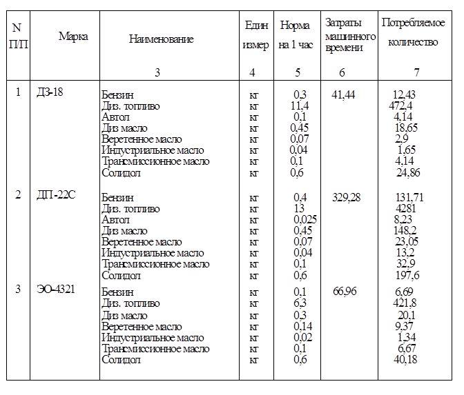
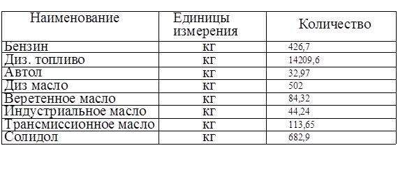
The results of the calculation of work with various types of soils are shown in Table 4.1.
Table 4.1 - List of volumes of earth masses
|
Soil name |
Quantity, m 3 |
|
|
Mound (+) |
Notch (-) |
|
|
1. Territory planning ground | ||
|
2. Displaced soil | ||
|
Including: | ||
|
a) when arranging road surfaces | ||
|
b) when replacing soil with fertile soil in landscaping areas | ||
|
3. Adjustment for compaction (residual loosening) | ||
|
Total suitable soil | ||
|
4. Lack of suitable soil | ||
|
5. Fertile soil, total | ||
|
Including: | ||
|
a) used for landscaping | ||
|
b) lack of fertile soil | ||
|
6. Total processed soil | ||
From this statement it can be seen that when carrying out work with the earth (during the vertical planning of the territory, when arranging paths and sites, when planting trees and shrubs), 7477 m 3 of soil is displaced (taking into account the correction for compaction). As a result, there is an excess of suitable soil. Fertile soil is not enough: 379 m 3 is required. It is required to transport 379 m 3 of fertile soil to the developed territory.
Table 5.1 continued
|
7. Rolling the soil with rollers in two approaches |
MTZ-320 Roller KVG-1.4 | |||||||
|
8. Sowing grass with a seeder |
MTZ-320 Seeder "Egedal" mod.83 |
bluegrass meadow, kg | ||||||
|
red fescue, kg | ||||||||
|
9. Sowing the lawn manually in places inconvenient for the passage of mechanisms | ||||||||
|
perennial ryegrass, kg | ||||||||
|
11. Watering the lawn with a watering machine |
5.1.1 Loosening the lawn base. The device of the lawn begins with loosening the base to a depth of 20 cm, depending on the conditions. Thanks to this operation, the base acquires a porous structure, which ensures good water and air exchange.
5.1.2 Leveling the ground. The operation is carried out in order to create a flat surface without depressions and elevations. Leveling is carried out mechanized and manually on areas of the lawn inaccessible to mechanisms. In this case, a rake is used, stones, weed roots, and debris are carefully selected from the top layer. The amount of plant land is determined by the thickness of the root layer, which is taken as 15 cm, therefore, 15 m 3 of plant land is needed per 100 m 2.
5.1.3 Manual spreading of vegetable soil. This operation is carried out by throwing the earth in those places where the mechanisms do not pass. Manual work in places is planned for 10% of the area.
5.1.4 Application of mineral fertilizers. The application of mineral fertilizers contributes to better and faster seed germination. The types of fertilizers used are shown in Table 5.2.
Table 5.2 - Mineral fertilizers
5.1.5 Harrowing the soil in two passes. After applying fertilizers and leveling the plant land, harrowing is carried out with a ZBS-1 harrow based on MTZ-82 to plant fertilizers to a depth of 3-5 cm and loosen the soil to obtain a finely cloddy structure.
5.1.6 Leveling the soil with a rake. Leveling is carried out with a selection of stones and roots in places that are inconvenient for mechanisms and their approach on medium soils.
5.1.7 Rolling the soil with rollers. Soil compaction is carried out by a KVG-1.4 roller based on MTZ-320, which allows lowering the soil before sowing, as well as crushing stones. Rolling is carried out in two passes with a roller.
5.1.8 Sowing seeds of lawn grasses. Sowing of seeds is carried out by the Egedal mechanism based on MTZ-320, as well as manually. In this area, the soil is fertile fresh sandy loam; the place is well lit, so the following grass mixture was used: meadow bluegrass - 30%, red fescue - 50%, perennial ryegrass - 20%.
Comparison of excavation volumes for cuts and embankments at a construction site is a balance of earth masses, which can be active if the volume of excavations exceeds the volume of embankments, and passive if the volume of excavations is less than the volume of embankments. In the first case, excess soil is removed from the construction site to dumps, in the second case, the soil missing for the construction of embankments is imported from outside.
Since the removal of soil from the site is undesirable, since it increases the time and cost of construction, one should strive to ensure that all soil from the excavations is placed without residue in the embankment, i.e. to maintain a zero balance on the site. To obtain such equality, it is necessary to determine the optimal level of the site layout, at which a zero balance of earth masses will be achieved.
The optimal layout mark, on both sides of which (top and bottom) there will be equal volumes of excavation and embankment when calculating volumes by squares (Fig. 2, a, b), is determined by the formula:
where H1, H2, H3, H4 are the marks of the natural surface of the site at the vertices common to one, two, three and four squares, respectively, m; n is the number of squares within the site.
When planning the site of a complex of structures, the optimal level of planning must be adjusted taking into account the additional volumes of soil required for the installation of permanent structures, and the volumes of soil displaced by the underground parts of the structures and communications under construction. The correction to this mark can be determined by the formula:
where Vi is the additional volume of soil (accepted with a plus when there is a surplus, and with a minus when there is a lack of soil), m3; F -- area of the planned site, m2.
After the end of the calculation, all the volumes of earthworks are reduced to a special sheet, called the summary balance of earth masses and consisting of two parts: the left - the arrival of the soil (P) and the right - the consumption of the soil (P). When P>P, the balance is positive, i.e. active, at P<Р баланс отрицательный, т.е. пассивный, и при П=Р баланс нулевой. Определив баланс земляных масс, составляют схемы потоков перемещения грунта из выемок в насыпи или в резервы.
The volumes of embankments and excavations of significant length (roadbed, dams, dams, etc.) are calculated using the longitudinal and transverse profiles of the structure. At characteristic points of the longitudinal profile, places of change in the slope of the terrain or the red (design) line, the structure is divided by vertical planes into parts, within which geometric bodies are obtained - prismatoids. The height of the prismatoid is equal to the length of the section between the sections, and the bases are the profiles of the structure in the places of the sections. This method is also sometimes referred to as the cross profile method.
The total volume of a structure is defined as the sum of the volumes of the prismatoids.
3. Consolidated balance earthen masses
The consolidated balance allows you to determine whether excess soil is removed from the site to the dump (at A> B), whether the missing soil is brought from the reserve (at B> A), where and in what volume the soil is moved from the planning excavation and from the pit, where the missing soil is brought priming.
The soil distribution plan supplements the master balance. It graphically shows where and in what size one or another elementary volume of soil is moved. To do this, on the site plan (without contour lines, broken down into squares), a line of zero work is applied, and the areas of excavation and embankment are indicated. In the upper left corner of each elementary figure, its number and the volume of soil in the figure are indicated. Indicate the volume of the pit, trench, as well as the volume of soil from the consolidated balance, which is taken out to the dump or brought from the reserve (quarry).
In the planning embankment or excavation, the figures most distant from the line of zero work are indicated, from which, in case of excess, the soil is taken to the dump, and in case of a shortage, the soil is brought from the reserve.
As a result, the soil distribution plan clearly shows the dynamics of its movement from the cut zones to the embankment zones, the supply of the missing and the removal of excess soil, its compliance with the consolidated soil balance.
To determine the missing soil in the embankment, subtract the excavation volume from the volume of the embankment: 211150-209156=1994 m 3 . We will get this missing volume from the trench: 1994-2016 \u003d -22 m 3, and we will take the remaining soil and soil from the pit to the dump: 4813.8 + 22 \u003d 4835.8 m 3
Table 2. Summary ground balance
The average range of soil movement is determined by the graph-analytical method.
The distance between the centers of gravity of the excavation and embankment is taken as the average range of soil movement. To find them, a site plan is drawn (without contour lines, broken down into squares), a line of zero work is applied, and the excavation and embankment areas are indicated. In the upper left corner of each elementary figure, its number and the volume of soil in the figure are indicated. Then plots of volumes for cut and fill are drawn: vertical and horizontal. The average lines of the volumes l x cf and l y cf are drawn through the graphs, vertical lines are drawn through the intersection points and the centers of gravity of the embankment and excavation are located at the intersections of the corresponding lines, as shown in the graphic part of the project.
4. Drawing up a statement of volumes of earthworks
Determine the scope of work on the development of soil at the construction site and select the mechanisms for their implementation. There are several main types of work.
An excerpt of a pit, trenches. The soil is developed in the pit (trenches) with the help of an excavator with its loading into vehicles for removal from the pit; with the help of an excavator backfill sinuses and laid out around the perimeter of the pit.
The soil is hauled by dump trucks to a planning embankment or dump.
The bottom of the pit is cleaned manually, with a bulldozer or a planner excavator to remove the shortage of soil. Backfilling of the sinuses is carried out using a bulldozer with soil developed by an excavator.
Simultaneously with backfilling, the soil is compacted in layers into the sinuses using manual pneumatic rammers.
Construction site layout. The soil is loosened using trailed tractor rippers, moved from the excavation to the embankment using a bulldozer or a scraper, depending on the average range of soil movement.
The soil in the planning embankment is leveled layer by layer using a bulldozer and compacted using trailed rollers.
Transportation of the missing soil from the reserve (quarry). The soil in the quarry is developed with the help of an excavator with its loading into vehicles. Soil is transported from the reserve by dump trucks.
Removal of excess soil from the site to the dump. The soil is loosened using trailed tractor rippers.
General layout of a construction site with a bulldozer. The selected scope of work and the corresponding mechanisms for each specific case are recorded in the statement of volumes and labor intensity of work, using the catalogs of mechanisms, the instructions in this manual and the data of ENiRE 2-1. When filling out the statement of volumes and labor intensity of work, it should be taken into account that the units of measurement of the volume of work for various processes must comply with ENiRE 2-1; the thickness of the soil layer when cleaning the bottom of the pit with a bulldozer is taken equal to 10 cm, and when cleaning manually - 5 cm; tamping of the backfill soil is carried out in layers up to 20 cm thick, therefore the scope of work is determined as Vo.z: 0.2 in m2; soil compaction in the leveling embankment is carried out in layers approximately 0.25 m thick, therefore the scope of work is determined as Vn/Ko: 0.25 in m2; The thickness of the plant layer can be taken equal to 15 cm.
The norm of time for soil compaction by rollers in ENiRE 2-1 is given for one penetration of the rink. It is advisable to take the compaction of the soil for six penetrations, so the time rate is multiplied by 6.
Labor costs in machine shifts and man-days are calculated based on the duration of the work shift. at 8.2 o'clock
Table 3. Bill of quantities.
| N | Name of works | Unit works | Count formula | Scope of work |
| 1 | The cut is growing. layer | 1000 m2 | A*B/1000 | 420 |
| 2 | Soil loosening | 100 m3 | Vv/100 | 2091,56 |
| 3 | Development and movement of soil with a scraper | 100 m3 | Vv/100 | 2091,56 |
| 4 | Layered soil compaction | 100 m3 | Vн/100 | 2111,5 |
| 5 | Development of a pit with an excavator a) with loading in t.s. b) snap | |||
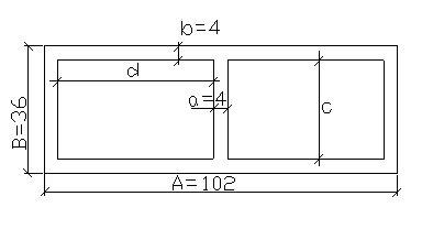
| 6 | Development of a trench with an excavator with arr. with a shovel | 100 m3 | (Vtr-a*b*H)/100 | 8,16 |
... - 3.1 tons. 11.2 List of operating materials for each type of mechanism 11.3 List of basic operating materials. 12Measures for safety in the performance of earthworks and the construction of foundations. Earthworks should be carried out only according to the approved project for the production of works. If there are underground works in the area of earthworks...
... (paragraph 3) stipulates that, within the framework of the arbitration process, the use of evidence obtained in violation of federal law. 2.3 Arbitrage practice protection of the rights legal entities when conducting inspections on the example of OAO Kotelnikovospetsstroy Having considered at the court session appeal OAO Kotelnikovospetsstroy for decision Arbitration Court Volgograd region from...