
Manipulator Crane Operating Instructions. What does the operating manual for a crane require from the operator. Labor protection requirements in emergency situations
After purchasing the CMU and registering it with Rostekhnadzor, the owner must familiarize himself with the operating instructions for the crane. This is necessary for the efficient operation of the device, as well as for the prevention of various breakdowns. Both the person who purchased the unit and the one who will work on it need to read the instructions. Then both the owner and the operator will not make the mistakes described in the document.
- Use of fluid not recommended by the manufacturer for the hydraulic system of manipulators. Because of this, the entire design of the CMU may fail.
- Neglect of daily and weekly faucet maintenance. If friction units are lubricated out of time, they wear out quickly. After a year of such maintenance, backlashes may appear, in which it will become dangerous to operate the crane.
- Systematic errors during manipulator control. For example, the wrong order of bringing the manipulator into position. The instructions describe the rules governing these actions. Due to control errors, operators often hit the cab and objects that are near the machine with the manipulator.
- Inappropriate use. For example, the driver may try to lift the car with a crane or push it out of the mud. Or use an arrow to drag a load along the surface. As a result of such actions, the crane experiences loads for which it was not intended, and may break.
- Lifting rules are not followed. With various movements of the manipulator, its parts must occupy the positions necessary for work. If these requirements are ignored, then the load on the nodes increases several times. Such actions, of course, lead to breakage of cranes.
- Incorrect alignment of manipulator supports during operation. These actions lead to the overturning of the entire machine, which endangers not only the operator, but also the surrounding people.
- Lack of heating of the hydraulic system in winter conditions. The procedure is necessary for the normal functioning of the manipulator. In the summer, it is not required, since when the crane is brought into working position, the system has time to warm up.
- CMU, in which there is no oil cooler, need a large capacity tank, since it is in it that the oil is cooled. It should be able to hold such a volume of liquid that the pump pumps out in about 2 minutes. Saving on the tank will lead to rapid wear of the entire hydraulic system of the manipulator.
Machine Maintenance
It is very important to study the maintenance manual for the system. The instructions stipulate the rules for both daily and weekly maintenance. The frequency can be specified not only in days, but also in hours.
The instructions also describe where the system needs to apply pressure lubrication. In some cases, you just need to apply it to the rubbing surfaces of the cranes. During the operation of the CMU, it is necessary to monitor the temperature of the liquid. At a critical value, the installation must be stopped and wait until it cools down. At 100 degrees, the lubricant begins to oxidize, due to which it loses its properties.
The hydraulic fluid is changed about once a year. The rules state that this period must be observed even if the crane has not been operated for the entire period. This is due to the hygroscopic properties of the liquid, which, when absorbing moisture, becomes an emulsion. When replacing the product, it is also necessary to change the used filters.
During this operation, attention is paid to the readings of the manometer. This device determines the degree of filter clogging. Under normal conditions of use of the manipulator, the pressure gauge needle practically does not change position. An indicator of a large clogging of the hydraulic system of the crane is the displacement of the arrow in the direction of high pressure.
Crane hydraulic fluid types and replacement procedure
 All-weather fluid is very convenient and can be used in the operation of many loader cranes. But if the crane is operated in regions where the difference between winter and summer temperatures is too large, you should buy both a summer and a winter product. The rules for choosing a winter solution for manipulators prescribe to take into account its pour point. It should be lower than the expected temperature in winter. Otherwise, the liquid will turn into a mass that will be unable to perform the functions assigned to it.
Do not use fluid that is not intended for use in a particular season. Summer will be too thick at low temperatures, causing damage to hoses, pump and other system components. Frozen valves will not be able to relieve pressure. Winter liquid in the heat, on the contrary, will not have a high viscosity. The hydraulic system of the machine in this case will overheat and fail. In addition, from overheating, the seals of the hydraulic parts of the system will dry out, as a result of which leaks and scoring in the hydraulic units are possible.
Before changing the fluid, be sure to look at the manual so as not to miss a single detail. CMU first folds into position for transportation. Then the drain plug is unscrewed.
After the old fluid is completely drained, a new one is filled. At the end of the procedure, the valve should be expanded several times to fill the system. There is no need to open any plugs for air release, since this function is performed by the tank breather.
The bottom of the hydraulic tank of the manipulator is equipped with a special recess with a plug. It regularly accumulates water and dirt, and the crane operator must drain it every week. If there is a lot of water, you need to add clean liquid through the filter to prevent dirt from entering.
Instructions for operators (drivers) on the safe operation of manipulator cranes.
1. General instructions for operators.
1.1. This Standard Instruction has been developed taking into account the requirements of the Rules for the Use of Technical Devices at Hazardous Production Facilities, approved by Government Decree Russian Federation dated December 25, 1998 No. 1540 (Collection of Legislation of the Russian Federation. 1999. No. 1. Art. 191), Rules for the Organization and Implementation production control for compliance with industrial safety requirements at a hazardous production facility, approved by Decree of the Government of the Russian Federation dated March 10, 1999 No. 263 (Collected Legislation of the Russian Federation. 1999. No. 11. Art. 1305), Rules for the Design and safe operation load-lifting cranes (PB 10-257-98)*, approved by the Decree of the Gosgortekhnadzor of Russia dated December 31, 1998 No. 79, and establishes the obligations of operators (crane operators) for the maintenance of loader cranes.
Rules.
1.2. Production instructions for operators (drivers) are developed on the basis of this Standard Instruction, agreed with the Gosgortekhnadzor of Russia, and may contain Additional requirements arising from the local conditions of operation of loader cranes, instructions for servicing loader cranes, their vehicles and safety devices set out in the operating manuals for loader cranes, their vehicles and safety devices.
1.3. Operators (drivers) who have been trained and have a certificate for the right to operate load-lifting cranes-manipulators must know:
1) manuals for the operation of cranes-manipulators and safety devices of manufacturers;
2) production instructions;
4) know the timing and results of preventive periodic inspections of the crane-manipulator and its individual mechanisms and assemblies carried out by locksmiths and electricians according to entries in the journal of periodic inspections.
6.3. Troubleshooting that occurs during the operation of the crane-manipulator is carried out at the request of the operator (driver). Other types of repairs are carried out in accordance with the preventive maintenance schedule.
7. Responsibility of the operator (driver) of the manipulator crane.
The operator (driver) of the loader crane is responsible for violation of the requirements production instructions and manuals for the operation of the crane-manipulator in the manner prescribed by law.
Approved
deputy
CEO
NPO "VNIIstroydormash"
Agreed
letter of Gosgortekhnadzor of Russia
STANDARD INSTRUCTIONS
FOR OPERATORS (MACHINE ENGINEERS) FOR SAFE OPERATION
LOADER CRANES
1. GENERAL PROVISIONS
1.1. This Standard Instruction has been developed taking into account the requirements of the Rules for the use of technical devices at hazardous production facilities, approved by Decree of the Government of the Russian Federation of December 25, 1998 N 1540 (Collected Legislation of the Russian Federation, 1999, N 1, Art. 191), Rules for organizing and exercising production control over compliance with industrial safety requirements at a hazardous production facility, approved by Decree of the Government of the Russian Federation dated March 10, 1999 N 263 (Collection of Legislation of the Russian Federation, 1999, N 11, art. 1305), Rules for the Design and Safe Operation of Hoisting Loader Cranes (PB 10-257 -98)< * >, approved by the Decree of the Gosgortekhnadzor of Russia dated December 31, 1998 N 79, and establishes the obligations of operators (crane operators) for servicing loader cranes.
1.2. Production instructions for operators (drivers) are developed on the basis of this Standard Instruction, agreed with the Gosgortekhnadzor of Russia, and may contain additional requirements arising from local operating conditions of loader cranes, instructions for servicing loader cranes, their vehicles and safety devices set forth in operating manuals for loader cranes, their vehicles and safety devices.
1.3. Operators (drivers) who have been trained and have a certificate for the right to operate load-lifting cranes-manipulators must know:
1) manuals for the operation of cranes-manipulators and safety devices of manufacturers;
2) production instructions;
3) arrangement of loader cranes, purpose, principles of operation and arrangement of nodes of mechanisms and safety devices of loader cranes;
4) arrangement of load-handling devices;
5) instruction on labor protection;
6) techniques and methods of providing first aid to the victims.
2. OBLIGATIONS OF THE OPERATOR (ENGINEER) BEFORE STARTING
CRANE WORK
2.1. Before starting work, the operator (driver) must make sure that all mechanisms, metal structures and other parts of the crane-manipulator are in good condition. In doing so, he must:
1) inspect the mechanisms of the crane-manipulator, their fastening and brakes, as well as the running gear, traction and buffer devices;
2) check the presence and serviceability of the mechanism guards;
3) check the lubrication of gears, bearings and ropes, as well as the condition of lubricators and glands;
4) inspect in accessible places metal structures and joints of boom sections and elements of its suspension (ropes, stretch marks, blocks, earrings, etc.), as well as metal structures and welded joints of the running frame (chassis) and the turning part;
5) inspect in accessible places the condition of the ropes and their fastening on the drum, boom, grab, as well as the laying of ropes in the streams of blocks and drums;
6) inspect the hook and its fastening in the holder;
7) check the serviceability of additional supports (retractable beams, jacks) and stabilizers;
8) check the availability and serviceability of safety devices and devices;
9) check the serviceability of the lighting of the crane-manipulator, buffer lights and headlights;
10) when accepting a hydraulically driven loader crane, inspect the drive system, flexible hoses, if used, pumps and safety valves on pressure lines.
2.2. The operator (driver) is obliged, together with the slinger, to check the compliance of the load-handling devices with the mass and nature of the load, their serviceability and the presence of stamps or tags on them indicating the carrying capacity, test date and number.
2.3. When accepting a working loader crane, the inspection must be carried out jointly with the operator (driver) handing over the shift. To inspect the crane-manipulator, the owner is obliged to allocate the necessary time to the operator (driver) at the beginning of the shift.
2.4. Inspection of the crane-manipulator should be carried out only when the mechanisms are not working.
2.5. When inspecting a crane-manipulator, the operator (driver) must use a portable lamp with a voltage of not more than 12 V.
2.6. After inspecting the loader crane before putting it into operation, the operator (driver), having made sure that the required approach dimensions are observed, is obliged to test all the mechanisms at idle and check the correct operation:
1) crane mechanisms and electrical equipment, if any;
2) safety devices and devices available on the crane;
3) brakes;
4) hydraulic systems.
2.7. If, during the inspection and testing of the crane-manipulator, faults or shortcomings in its condition that impede safe operation are detected, and it is impossible to eliminate them on their own, the operator (crane operator), without starting work, must report this to the engineering and technical worker responsible for the maintenance of the crane - the manipulator is in good condition, and notify the person responsible for the safe performance of work with cranes-manipulators.
2.8. The operator (driver) should not start working on the loader crane if there are the following faults:
1) cracks or deformations in the metal structures of the crane;
2) cracks in the boom suspension elements (earrings, rods, etc.);
3) the absence of cotter pins and previously existing clamps in the places of attachment of the ropes or the weakening of the attachment;
4) the number of breaks in the wires of the boom or cargo rope or surface wear exceeds the norm established by the operation manual of the crane-manipulator, there is a broken strand or other damage;
5) defects in the load lifting mechanism or the boom lifting mechanism that endanger the safety of work;
6) damage to the brake parts of the load lifting mechanism or the boom lifting mechanism; wear of hooks in the throat, exceeding 10% of the initial section height, malfunction of the device that closes the hook throat, violation of the fastening of the hook in the cage;
7) damage or incompleteness of additional supports, malfunction of stabilizers for automobile and other loader cranes with a sprung undercarriage;
8) damage to cable blocks and devices that prevent the rope from exiting the block's strands.
2.9. Before starting work, the operator (driver) must:
1) get acquainted with the project for the production of work with cranes-manipulators, technological maps of loading, unloading and warehousing of goods;
2) check the condition of the site for the installation of a crane;
3) make sure that there is no power line at the work site or it is located at a distance of more than 30 m;
4) obtain a work permit for the operation of a loader crane at a distance closer than 30 m from the power line;
5) check the sufficiency of illumination of the working area;
6) make sure that the slingers have certificates and distinctive signs.
2.10. Having accepted the loader crane, the operator (driver) must make an appropriate entry in the logbook and, after receiving the assignment and work permit from the person responsible for the safe performance of work by loader cranes, begin work.
2.11. Permission to put into operation caterpillar and pneumatic wheel cranes-manipulators after moving them to a new facility is issued by an engineering and technical worker for supervision of the safe operation of cranes-manipulators on the basis of checking the condition of the crane-manipulator and ensuring safe working conditions with an entry in the logbook.
3. OBLIGATIONS OF THE OPERATOR (MACHINE MANAGER) DURING
CRANE WORK
3.1. When operating a loader crane, the operator (driver) must be guided by the requirements and instructions set out in the operation manual of the loader crane and the production instructions.
3.2. The operator (driver) during the operation of the crane-manipulator mechanisms should not be distracted from their direct duties, as well as clean, lubricate and repair the mechanisms.
3.3. If it is necessary to leave the crane-manipulator, the operator (driver) is obliged to stop the engine that sets the mechanisms of the crane-manipulator in motion and remove the ignition key from the automobile cranes-manipulators. In the absence of an operator (driver), the trainee and other persons are not allowed to operate the loader crane.
3.4. Before making any movement with a loader crane, the operator (driver) must make sure that the trainee is in a safe place, and there are no strangers in the work area of the loader crane.
3.5. If there was a break in the work of the mechanisms of the crane-manipulator, then before turning them on, the crane operator is obliged to give a warning sound signal.
3.6. The movement of the crane-manipulator under the power line should be carried out with the boom lowered (in the transport position).
3.7. During the movement of the loader crane with a load, the position of the boom and the lifting capacity of the loader crane should be set in accordance with the instructions contained in the operation manual of the loader crane. It is not allowed to simultaneously move the crane-manipulator and turn the boom.
3.8. The operator (driver) is obliged to install the crane-manipulator on all additional supports in all cases when such an installation is required according to the passport characteristics of the crane-manipulator; at the same time, he must ensure that the supports are in good order and that strong and stable linings are placed under them, which are an inventory of the crane-manipulator. It is not allowed to place random objects under additional supports.
3.9. It is forbidden for the operator (driver) to be in the cab when the crane-manipulator is installed on additional supports, as well as when it is released from the supports.
3.10. Installation of a crane-manipulator on the edge of the slope of the pit (ditch) is allowed provided that the distances from the beginning of the slope of the pit (ditch) to the edge of the supporting contour of the crane-manipulator are not less than those indicated in the table. If these distances cannot be observed, the slope must be reinforced. The conditions for installing a crane-manipulator on the edge of the slope of the pit (ditch) must be specified in the project for the production of work by cranes-manipulators.
MINIMUM DISTANCE FROM THE BEGINNING OF THE SLOPE OF THE PIT (DITCH)
TO THE EDGE OF THE SUPPORT CONTOUR OF THE CRANE-MANIPULATOR
WITH NON-BULK GROUND, M
┌───────────────────────────────────────────────── ────────────────┐ │ Depth │ Ground │ │ excavation ├───────────┬───────────┬───── ───────┬─────────┬─────────┤ │(ditches), m│sandy and│sandy│loamy│clay│loess│ │ │gravel │ │ │ │ dry ┼─────────┼──────────┤ │1 │1.5 │1.25 │1.00 │1.00 │1.0 │ ├─────── ─────┼──────────┼─────────────────────────────────────┼ ────────┤ │2 │3.0 │2.40 │2.00 │1.50 │2.0 │ ├───────────┼────── ─────┼──────────┼─────────────────────────────────┤ │3 │4.0 │3.60 │3.25 │1.75 │2.5 │ ├─────────────────────────────── ─────┼───────────┼──────────┼───────────────┤ │4 │5.0 │4.40 │4, 00 │3.00 │3.0 │ ├─────────────────────────────────────────── ──────┼─────────┼─────────┤ │5 │6.0 │5.30 │4.75 │3.50 │3.5 │ └ ───────────┴────────────────────────────────────┴───── ─────┴─────────┘3.11. Loader cranes for construction and installation work should be installed in accordance with the project for the production of work by cranes.
3.12. The installation of loader cranes should be carried out on a planned and prepared site, taking into account the category and nature of the soil. It is not allowed to install loader cranes to work on freshly poured uncompacted soil, as well as on a site with a slope exceeding the allowable for this loader crane in accordance with the operation manual of the loader crane.
3.13. Loader cranes should be installed in such a way that during operation the distance between the rotary part of the loader crane in any position and buildings, stacks of goods and other objects is at least 1 m.
3.14. The operator (driver) is prohibited from unauthorized installation of a loader crane to work near a power line (until receiving an assignment from a person responsible for the safe performance of work by loader cranes).
3.15. The operator (driver) must work under the direct supervision of the person responsible for the safe performance of work by cranes-manipulators, when loading and unloading gondola cars, when moving cargo by several cranes-manipulators, near the power line; when moving cargo over ceilings, under which production or service premises are located, where people can be; when moving a load for which a slinging scheme has not been developed, as well as in other cases provided for by the projects for the production of works or technological regulations.
3.16. The movement of goods over the ceilings, under which industrial, residential or service premises are located, where people can be located, is not allowed. In some cases, cargo can be moved over the ceilings of industrial or office premises in which people are located, after the development of measures (in agreement with the state technical supervision authorities) that ensure the safe performance of work, and under the guidance of a person responsible for the safe performance of work by cranes-manipulators.
3.17. Joint work on moving cargo by two or more loader cranes may be allowed only in individual cases and must be carried out in accordance with the project for the production of works or technological map, which should contain schemes for slinging and moving cargo, indicating the sequence of operations, the position of cargo ropes, and also contain requirements for site preparation and other instructions for the safe movement of cargo.
3.18. When moving goods, the operator (driver) must be guided by the following rules:
1) it is possible to work as a crane-manipulator only at the signal of the slinger. If the slinger gives a signal, acting in violation of the requirements of the instructions, then the crane operator should not perform the required maneuver of the loader crane on such a signal. Both the operator (driver) and the slinger who gave the wrong signal are responsible for damage caused by the action of the loader crane due to the execution of an incorrectly given signal. The exchange of signals between the slinger and the operator (driver) must be carried out in accordance with the procedure established at the enterprise (in the organization). The signal "Stop" the operator (driver) is obliged to carry out regardless of who gives it;
2) it is necessary to determine the load capacity of the crane-manipulator for each departure according to the load-carrying capacity indicator;
3) before lifting the load, the slinger and all persons near the loader crane should be warned about the need to leave the area of the load being moved, the possible fall of the load and the lowering of the boom. It is possible to move the load only if there are no people in the work area of the crane-manipulator. The specified requirements must be met by the operator (driver) also when lifting and moving the grab. The slinger may be near the load during its lifting or lowering, if the load is at a height of not more than 1 m from the platform level;
4) it is allowed to load and unload trolleys, motor vehicles and trailers for them, railway gondola cars and platforms only if there are no people on the vehicles, which the operator (driver) must first verify;
5) install the hook of the lifting mechanism above the load in such a way that when lifting the load, oblique tension of the load rope is excluded;
6) when lifting the load, it is necessary to first lift it to a height of no more than 200 - 300 mm to make sure that the slinging is correct, the loader crane is stable and the brakes are working properly, after which you can lift the load to the desired height;
7) when lifting the load, the distance between the hook cage and the blocks on the boom must be at least 500 mm;
8) loads moving in the horizontal direction (handling devices) should be preliminarily raised by 500 mm above the objects encountered on the way;
9) when lifting the boom, it is necessary to ensure that it does not rise above the position corresponding to the smallest working reach;
10) when moving cargo located near a wall, column, stack, railway car, car, machine or other equipment, you should first make sure that there is no slinger and other people between the transported cargo and the specified parts of the building, vehicles or equipment, as well as the impossibility hitting walls, columns, wagons, etc. with an arrow or a moving load. Loading into gondola cars, platforms and trolleys, as well as removing them should be done without disturbing the balance of gondola cars, trolleys and platforms;
11) the movement of small-piece cargoes should be carried out in containers specially designed for this, while the possibility of falling out of individual cargoes should be excluded, lifting bricks on pallets without fencing is allowed only when loading and unloading (on the ground) motor vehicles, trailers, railway gondola cars and platforms;
12) before lifting a load from a well, ditch, trench, pit, etc. and before lowering the load into them, by lowering the free (unloaded) hook, first make sure that at its lowest position on the drum at least one and a half turns of the rope remain wound, not counting the turns under the clamping device;
13) stowage and dismantling of cargo should be even, without violating the dimensions established for warehousing cargo and without blocking the aisles;
14) it is necessary to carefully monitor the ropes; when they fall from drums or blocks, loops are formed or ropes are damaged, the operation of the crane-manipulator should be suspended;
15) if the crane-manipulator has two lifting mechanisms, their simultaneous operation is not allowed. The hook of a non-working mechanism must always be raised to the highest position;
16) slinging of loads must be carried out in accordance with the slinging schemes. For slinging, slings should be used that correspond to the mass and nature of the load being lifted, taking into account the number of branches and their angle of inclination; general purpose slings are selected so that the angle between their branches does not exceed 90 °;
17) when operating a crane-manipulator with a grab designed for bulk and lumpy materials, it is not allowed to transship material whose largest size of pieces exceeds 300 mm, and also if the bulk mass exceeds the value established for this grab. Transshipment of piece cargo can only be carried out with a special grab;
18) the operation of grab cranes is allowed in the absence of people in their area of operation. Ancillary workers may be allowed to perform their duties only after a break in the operation of the crane, after the grab is lowered to the ground;
19) it is allowed to lower the transported cargo only to the place designated for this, where the possibility of falling, overturning or sliding of the installed cargo is excluded. Linings of appropriate strength must be preliminarily laid at the place of installation of the load. Stowage and disassembly of goods should be carried out evenly, without violating the dimensions established for the storage of goods and without blocking the aisles.
3.19. Manipulator cranes at a distance of less than 30 m from the lifting retractable part of the crane-manipulator in any of its positions, as well as from the load to the vertical plane formed by the projection onto the ground of the nearest overhead power line wire with a voltage of 42 V or more, should be carried out along with approval for safe working conditions. The procedure for organizing work near the power line, issuing work permits and instructing workers is established by order of the owner of the loader crane. Safe distances from parts of the crane or load in any position to the nearest power line wire are: at voltage up to 1 kV - 1.5 m, from 1 to 20 kV - at least 2 m, from 35 to 110 kV - at least 4 m , from 150 to 220 kV - at least 5 m, up to 330 kV - at least 6 m, from 500 to 750 kV - at least 9 m.
In the event of a production need, if it is impossible to maintain the specified distances, work with a loader crane in the restricted area can be carried out with the power line disconnected according to a work permit, which indicates the time of work.
The operator (crane operator) should not start work if the person responsible for the safe performance of work with loader cranes did not ensure the fulfillment of the working conditions provided for in the work permit, did not indicate the installation location of the loader crane and did not make the following entry in the watch log: "Installation I checked the crane-manipulator at the place indicated by me. I authorize the work (date, time, signature)."
When operating cranes at existing power plants, substations and power lines, if work using cranes is carried out by personnel operating electrical installations, and operators (crane operators) are on the staff of the power company, a work permit for work near live wires and equipment is issued operator (crane operator) by a person responsible for the safe performance of work by loader cranes.
The work of cranes-manipulators under non-disconnected contact wires of urban transport can be carried out while observing the distance between the boom of the crane-manipulator and the contact wires of at least 1 m when installing a limiter (stop) that does not allow reducing the specified distance when lifting the boom.
3.20. The operator (driver) can start work in explosion and fire hazardous areas or with poisonous, caustic goods only after receiving a special (written) instruction from the person responsible for the safe performance of work with loader cranes.
3.21. During the performance of work, the operator (driver) is prohibited from:
1) allow random persons who do not have the rights of a slinger to tie or hook cargo, as well as use lifting devices that do not correspond to the mass and nature of the cargo, without tags or brands. In these cases, the operator (driver) must stop working with a loader crane and notify the person responsible for the safe performance of work with loader cranes;
2) to lift a load, the mass of which exceeds the load-carrying capacity of the crane-manipulator for a given departure. If the operator (driver) does not know the mass of the load, then he must obtain in writing information about the actual mass of the load from the person responsible for the safe performance of work with loader cranes;
3) lower the boom with the load until the departure, at which the load-carrying capacity of the crane-manipulator will be less than the mass of the load being lifted;
4) to produce sharp braking when turning the boom with a load;
5) to drag cargo along the ground, rails and logs with the hook of a crane-manipulator with the ropes inclined, as well as move railway cars, platforms, trolleys or carts with the help of a hook;
6) use a hook or grab to tear off a load covered with earth or frozen to the ground, embedded with other loads, reinforced with bolts, filled with concrete, etc.;
7) release the load-handling devices (slings, chains, tongs, etc.) pinched by the load with a crane-manipulator;
8) lift reinforced concrete products with damaged hinges, improperly strapped (tied) cargo in an unstable position, as well as in containers filled above the sides;
9) lay the load on electric cables and pipelines, as well as on the edge of the slope of a ditch or trench;
10) lift a load with people on it, as well as a load supported by hands;
11) transfer the control of the crane-manipulator to persons who do not have the right to control the crane-manipulator, as well as allow students and trainees to independently control the crane-manipulator without their supervision over them;
12) load and unload the car while the driver or other people are in the cab;
13) lift cylinders with compressed or liquefied gas that are not placed in special containers;
14) deliver cargo into window openings and onto balconies without special receiving platforms or special devices;
15) lift the load directly from the place of its installation (from the ground, platform, stack, etc.) with a boom winch;
16) use limit switches as working bodies for automatic stop of mechanisms;
17) work with out of action or faulty safety devices and brakes.
3.22. In the event of malfunctions, the operator (driver) is obliged to lower the load, stop the work of the loader crane and inform the person responsible for the safe performance of work with loader cranes. The operator (driver) must also act in the following cases:
1) when approaching a thunderstorm, strong wind, the speed of which exceeds the permissible for this crane-manipulator and specified in its passport;
2) in case of insufficient illumination of the place of work of the crane-manipulator, heavy snowfall or fog, as well as in other cases when the operator (driver) poorly distinguishes the signals of the slinger or the load being moved;
3) when the air temperature is below the permissible minus, indicated in the passport of the crane;
4) when twisting the ropes of the cargo chain hoist.
4. OBLIGATIONS OF THE OPERATOR (ENGINEER) IN EMERGENCY SITUATIONS
4.1. In case of loss of stability of the crane-manipulator (ground subsidence, breakage of the outrigger, overload, etc.), the operator (driver) must immediately stop lifting, give a warning signal, lower the load to the ground or platform and establish the cause of the emergency.
4.2. If the elements of the crane-manipulator (boom, ropes) are energized, the operator (driver) must warn the workers about the danger and move the boom away from the wires of the power line. If this is not possible, then the operator (driver) must leave the crane without touching the metal structures and observing personal safety measures against electric shock (in accordance with the operating manual for the crane).
4.3. If, during the operation of the crane-manipulator, the worker (slinger) came into contact with live parts, the operator (driver) must first of all take measures to free the victim from the action of electric current, observing personal safety measures, and provide the necessary first aid.
4.4. In the event of a fire on the crane-manipulator, the operator (driver) is obliged to immediately call the fire brigade, stop work and start extinguishing the fire, using the fire extinguishing equipment available on the crane-manipulator.
4.5. In the event of natural disasters (hurricane, earthquake, etc.), the operator (driver) must stop working, lower the load to the ground, leave the crane and go to a safe place.
4.6. In the event of other emergencies, the operator (driver) must comply with the safety requirements set forth in the operation manual of the loader crane.
4.7. If during the operation of the crane-manipulator an accident or an accident occurred, the operator (driver) must immediately notify the person responsible for the safe performance of work by cranes-manipulators, and ensure the safety of the situation of the accident or accident, if this does not represent danger to human life and health.
4.8. The operator (engineer) is obliged to make an entry in the logbook about all emergencies and notify the engineering and technical worker responsible for maintaining the loader cranes in good condition.
5. OBLIGATIONS OF THE OPERATOR (MACHINE ENGINEER) AT THE END
CRANE WORK
5.1. At the end of the work of the crane-manipulator, the operator (driver) must comply with the following requirements:
1) do not leave the load or grab hanging;
2) place the crane-manipulator in the place intended for parking, slow it down and lock the cab;
3) set the boom and hook to the position specified in the operation manual of the crane;
4) stop the engine;
5) enter in the logbook information about the identified defects and malfunctions of the units and elements of the crane.
5.2. When the crane-manipulator operates in several shifts, the operator (crane operator) handing over the shift must inform his shifter about all malfunctions in the operation of the crane-manipulator and hand over the shift by making an appropriate entry in the logbook.
6. LOADER CRANE MAINTENANCE AND CARE
6.1. When servicing a loader crane, the operator (driver) must comply with the requirements set forth in the operation manual for the loader crane.
6.2. The operator (driver) is obliged:
2) timely lubricate all mechanisms of the crane-manipulator and ropes;
3) know the timing and results of the technical examinations and maintenance (TO-1, TO-2, TO-3, CO) of the crane-manipulator;
4) know the timing and results of preventive periodic inspections of the crane-manipulator and its individual mechanisms and assemblies carried out by locksmiths and electricians according to entries in the journal of periodic inspections.
6.3. Troubleshooting that occurs during the operation of the crane-manipulator is carried out at the request of the operator (driver). Other types of repairs are carried out in accordance with the preventive maintenance schedule.
7. RESPONSIBILITY
The operator (driver) of the loader crane is responsible for violation of the requirements of the production instructions and the operation manual of the loader crane in the manner prescribed by law.
URV550 SERIES - Model 2013. The first UNIC CMU model with reversible outriggers. It has a maximum load capacity of 5,050 kg at a working radius of 2.5 m.
Specifications
The first model to feature reversible utrigers and a new security system. Designed for mounting on heavy duty trucks. The maximum load capacity of the KMU is 5,050 kg at a working radius of 2.5 m. It has a 3-, 4- or 5-section, hexagonal, telescopic, full-turn (360 without restrictions) boom with a 4-cable hook suspension. The outriggers extend up to a width of 4.32 m. The extension of the outriggers in width is manual, vertically hydraulic.
At the request of the client, this series can be supplied with a uni-hook (automatically folding) and with rear outriggers.
Main characteristicsURV550 series:
|
Name |
||||
| Number of boom sections | ||||
| Load moment, tm | ||||
| Working radius, m | ||||
| Maximum load capacity at a working radius of 2, m, kg | ||||
| Maximum load capacity at maximum working radius, kg |
750 at 11.0 m |
|||
| Boom length, m | ||||
| Boom extension speed, m/s | ||||
| Boom lifting speed from 1 to 78 degrees, sec. | ||||
| Hook lifting height, m | ||||
| Lowering the hook below ground level, m | ||||
| Boom angle, deg. |
360 unlimited |
|||
| Column rotation speed, rpm. | ||||
| Cargo rope with a diameter of 10 mm, length, m | ||||
| Load winch force, kN | ||||
| Maximum width of extended outriggers, m | ||||
| Productivity of the hydraulic pump at 1400 rpm, l/min | ||||
| Pressure in the hydraulic system, MPa | ||||
| Hydraulic tank capacity, l | ||||
The operating manual contains the rules for the operation, control and maintenance of the crane-manipulator unit (CMU) UNIC.
Before operating the CMU, it is necessary to carefully study this instruction manual.
If you encounter difficulties during operation, please contact your sales representative or an authorized service center.
◆ Contacting the service:
When contacting a service center or ordering spare parts, you must provide the model, specification, serial number, date of manufacture and type of vehicle on which the CMU is installed.
◆Information plate indicating the CMU model is located on the side of the column.
ABOUT MANUAL 6
1. GENERAL SAFETY 7
2. SAFETY PRECAUTIONS 8-17
2.1. Before you start 8
2.2. During work 12
2.3. After work 18
3. PURPOSE OF THE MAIN EQUIPMENT 19-22
4. PLAQUES 23-26
4.1. Placement of signs 23
4.2. Label content 24
5. GENERAL PROVISIONS 27-30
5.1. Installation behind the cab 27
5.2. Lifting a Load with the Boom Forward 27
5.3. Lifting a load with the boom position "Side" 27
5.4. Lifting a load with the boom position "Back" 27
5.5. Cargo weight 28
5.6. Load 28
5.7. Load capacity 28
5.8. Working radius 28
5.9. Arrow length 28
5.10. Boom angle 28
5.11. lift height 28
5.12. Outrigger extension 29
5.13. Boom section extension order 30
6. LOAD HIGH PERFORMANCE 31
6.1. Load-altitude characteristics 31
7. CONTROL DEVICES 32-47
7.1. Location of control devices 32
7.2. Automatic accelerator 34
7.3. Hand throttle 35
7.4. Horn 36
7.5. Hook lift limiter 37
7.6. How the hook lift limiter works 38
7.7. Boom angle indicator 41
7.8. Load indicator 43
7.9. Hook lock 45
7.10. Automatic stop of unwinding of the cargo rope 45
7.11. Load moment limiter 46
7.12. Safety valves 46
8. OPERATION OF CMU 48-66
8.1. Switching on the pump 48
8.2. Installing outriggers 50
8.3. Changing the angle of the boom 54
8.4. Raising and lowering a load 55
8.5. Telescoping boom 57
8.6. Boom swing 57
8.7. Folding outriggers into transport position 59
8.8. Bringing the crane-manipulator into transport position 66
9 Daily check before starting work 67-76
9.2 Wash 68
9.3. Checking the swing bearing 69
9.4. Changing the oil filter 69
9.5. Replacing the cargo rope 70
9.6. Replacing Consumables 74
9.7. Caution when welding work 74
9.8. Hinge Caution 75
9. LUBRICATION 77-82
9.1. Relubrication 77
9.2 Oil change 80
9. MAIN FEATURES 83-86
ABOUT THE GUIDE
The crane installations mentioned in this manual differ in the way the hook is folded and the remote (radio or cable) control. Each modification is described in detail in this manual.
Before starting the work of the CMU from remote control see the "Remote Control Guide".
1. Designation of modifications The main differences of each modification of the CMU are displayed in this manual.
The modification is divided into two categories according to the way the outriggers are folded.
Designation of KMU models
The model range of CMU UNIC URV630 series differs in the number of sections in the boom.
(KMU model) (Number of sections in the boom)
URV553 - 3
URV554 - 4
URV555 - 5
Follow the safety rules at work!
★ To prevent accidents, please read the precautions in this manual carefully.
★ Most crane accidents occur when the safety devices are tampered with and not
observance of elementary rules of their operation and maintenance.
Requirements
◆ Do not ignore the inscriptions and given in this manual, as they indicate important information for ensuring safety when operating the CMU.
Failure to heed this warning may result in accidental consequences, injury or death.
Neglect of this warning may cause damage to the CMU.
◆ Keep the manual in an easily accessible place.
◆ Failure to follow the rules of operation and maintenance of the CMU specified in this manual may lead to a malfunction of the CMU, a reduction in its service life, and even an accident. Please note that in this case you will lose the right to warranty service.
life even during the warranty period.
◆ To prevent injury or death of the CMU operator and people in close proximity to the manipulator crane as a result of an operational error, it is necessary to study the warning signs on the CMU.
◆ Do not make changes to the CMU device yourself.
★ If you want to upgrade the CMU, please contact a UNIC dealer or a certified UNIC Service Center.
★ UNIC is not responsible for accidents caused by unauthorized intervention in the CMU device.
BEFORE STARTING WORK
Use a hard hat, safety shoes and gloves.
★ Do not wear baggy clothing and accessories that can get caught on the control handles and parts of the crane - manipulator, as well as
work clothes soaked with oil, which may catch fire. Before starting work, check the CMU and slinging devices.
★ Using damaged slings may cause the load to fall. Before starting work, check the crane - manipulator.
★ If a problem is found, fix it immediately.
Make sure the safety devices are working.
★ Before starting the CMU, make sure that the hook lift limiter is turned on.
Keep a safe distance from power lines to avoid electric shock.
★ CMU is not electrically isolated.
Do not operate the crane during thunderstorms and when the wind speed exceeds 10 m/s.
★ Using the loader crane during strong winds may cause the load to fall or the loader crane to overturn.
The presence of strangers in the work area of the Cabinet of Ministers is unacceptable.
★ Follow the safety measures at work, observing strict control over the territory located in the work area.
Make sure the surface on which the outriggers are mounted is firm and level.
★ When installing the outriggers on an uneven surface, place flat wooden or steel stands under the outrigger plates to maintain proper stability. When operating a crane-manipulator on loose soil, it is necessary to add dry sand,
rubble or gravel. When installing outriggers, do not allow the front wheels of the crane-manipulator to be separated from the supporting surface.
Work with an incorrectly installed crane - manipulator can lead to breakage of outriggers and its overturning when working with a load.
zom.
For optimal use of the loader crane, the outriggers must be fully extended to their maximum width.
★The stability of the loader crane is affected by the extension width of the outriggers. Remember that when the outriggers are not fully extended, the carrying capacity of the CMU is sharply reduced. Do not place your feet under the outrigger plates as this may result in injury. Drive carefully
hook when you release the hook.
★Do not confuse the direction of operation. Lifting the hook by mistake can damage the loader crane.
Do not attempt to adjust or repair hydraulic equipment yourself.
DURING WORK
Always make sure that the hook is not overloaded. Make sure the hook lift limiter is engaged.
★Remember to lower the hook when extending the boom.
★If the hook hits the boom head, it may damage the rope and block in the boom head and cause the load to fall.
Drive the CMU slowly and without sudden movements.
★A sharp jerk when working with a lifted load creates a strong dynamic load on the CMU units and can lead to damage
or overturning of the crane.
★If the control lever does not return to the neutral position after releasing it, lubricate its attachment points or repair it. Control the CMU at low speed.
★When rotating the CMU string at high speed, it leads to the appearance of excessive dynamic loads and an increase in the working
dius.
If the engine speed is too low, increase it with the accelerator lever.
★Working the CMU at too low a speed may cause unstable operation of the engine, which will cause the load to oscillate and interfere with the proper control of the CMU. Do not allow persons to be in the vehicle cabin during CMU operation.
★Inadvertently pressing the gas pedal may cause an unexpected increase in the speed of the CMU, which may lead to an accident.
Do not stand under the boom and do not touch the moving parts of the CMU. Do not raise outriggers with load raised or boom extended.
★This may cause the crane to overturn.
Overloading of CMU is strictly prohibited.
★It is forbidden to lift a load that exceeds the nominal weight for a given boom reach. CMU operation exceeding the permissible load can lead to damage or overturning of the crane-manipulator.
★Be especially careful when turning the load from the rear position or back to the rear position. Remember that in this
the position of the crane-manipulator is particularly unstable. Pulling the load is strictly prohibited.
★It may cause damage to parts of the boom, column, and lifting cylinder. Do not leave the workplace when the load is lifted.
★Lower the load to the surface before leaving the job site.
When lifting a load that is close to the maximum permissible mass, the operator must make sure that the crane is stable -
manipulator and in the reliability of securing the load.
★When the load is off the ground, stop lifting for a while to make sure the load is kept horizontal and the crane is
the manipulator remains stable. Only then continue lifting the load.
★When lowering the load, before contact with the ground, it is necessary to reduce the speed of lowering the load. Do not stand on the lifted load.
★It may cause the cargo to fall.
STANDING UNDER A LOADED LOAD IS FORBIDDEN.
When working with a load below the surface, lower it more slowly than when working above the surface.
★When lowering the load, make sure that there are always at least three turns of rope on the load winch drum.
Do not allow the load rope to unwind without tension on the surface, which will cause it to wind unevenly on
cargo winch drum.
★This will later cause a sharp jerk during operation and lead to a sharp reduction in the life of the rope.
★The winding of the first layer of rope around the drum must be smooth and tight. If necessary, adjust the loops of the rope
wooden mallet. To avoid burns, avoid contact with the oil tank.
★During CMU operation, the oil in the tank heats up. This may cause a burn.
When the temperature of the hydraulic oil reaches more than 80ºС, stop the operation of the CMU.
★Oil temperature rises rapidly when repeatedly lifting and lowering a load to a great height.
★High temperature hydraulic oil can damage high pressure hydraulic hoses and hydraulic seals.
Lindrov.
Make sure the boom and outriggers are folded and the hook is secured before driving.
★Make sure the outriggers are fully retracted before driving. Check that the blue mark on the lever
extension of the outriggers was fully visible.
★Make sure that the outriggers are securely fixed with the stopper.
★Traveling with improperly secured outriggers, boom and hook may cause a serious accident.
Disengage the power take-off.
★When driving with the power take-off engaged, the hydraulic pump will operate and damage may result.
hydraulic system and pump failure.
★ For a CMU with an automatic hook folding system, the column rotation brake will not work in this mode, which can lead to the rotation of the unit. Do not service the CMU until the oil has cooled down.
★After CMU operation, the oil temperature is still very high. In addition, the oil in the system remains under pressure. Unscrewing the drain
plugs or filters may cause oil splashing.
PURPOSE OF THE MAIN EQUIPMENT
★ The figure shows a CMU with a 4-section boom, with a Unikryuk. Other CMUs of this series may differ from it in the number of sections and the presence of radio control.
★ The figure shows the CMU installed behind the cab of the vehicle. CMU installation options may be different.
★ The figure does not show the state of the CMU, ready for transportation.
Purpose of the main equipment of CMU UNIC550
1. Arrow
Provides movement of cargo in the working area. Extends and retracts with hydraulic cylinders.
2. Turning column
This is the vertical part of the crane installation, on which the boom, cargo winch, and hydraulic cylinder for changing the angle of the boom are installed. The column is rotated by a rotary mechanism.
3. Foundation of the Cabinet of Ministers
Mounted on the car frame.
4. Cargo winch
By means of a hydraulic motor, it raises and lowers the load with a rope.
5. Rotary mechanism
Turns the column by means of a hydraulic motor.
6. Lift cylinder
Raises and lowers the arrow.
7. Telescoping hydraulic cylinder
Extends and retracts boom sections.
8. Outriggers (outriggers)
Outriggers support the crane manipulator in a stable position during operation.
9. Lever control for changing the angle of the boom
Designed to change the angle of the boom.
10. Control lever for cargo winch
Controls the winch, allowing the hook to be raised and lowered.
11. Boom telescoping lever
Operates hydraulic cylinders to extend and fold the boom.
12. Column rotation control lever
Controls the hydraulic motor for turning the column, allowing the CMU to perform rotational movements around its axis.
13.14. Outrigger control levers
They control the extension and retraction of the outriggers.
15. Hook
To secure the load.
16. Accelerator lever
Designed to control engine speed.
17 . Hook lift limiter (with standard equipment)
When the hook rises close to the boom head, the emergency stop of the CMU is activated to prevent the breakage of the cargo
rope.
17 . Hook lift limiter (with Uni-hook kit)
When the hook rises close to the boom head, the work of the CMU stops to prevent the load rope from breaking.
18. Capacity indicator
Shows the weight of the lifted load.
19. Warning signal
When the horn button is pressed, the car horn is turned on. Designed to warn people in the work area.
20. Cargo rope
Designed to lift a load.
21. Selection box lever
power It is intended for switching on the power take-off box of the crane-manipulator.
23. Load scale
Shows the permitted load value corresponding to the length of the extended boom and its angle of inclination.
24. Hour meter
25. Oil tank
26. Automatic stop of the unwinding of the cargo rope (holding the cargo rope on the drum of the cargo winch)
Designed to disable the operation of the cargo winch in the mode of "unwinding the cargo rope", when the amount of the cargo rope on the drum of the cargo winch has decreased to three turns.
29. Level (inclinometer)
Designed to determine the horizontal position of the crane-manipulator.
Purpose of the main equipment
Load moment limiter.
The load moment limiter of the ML series is installed on the CMU UNIC.
Purpose:
In order to prevent destruction and (or) overturning of the CMU, a load capacity limiter (load moment limiter) of the ML series is installed, which automatically disables the mechanisms for lifting the load and changing the outreach in the event of lifting a load whose mass exceeds the carrying capacity for a given reach. After the load moment limiter is triggered, it is possible to lower the load or turn on other mechanisms to reduce the load moment, and turn on the mechanisms that increase the load moment.
Electronic control unit (ECU).
Designed to collect information coming from sensors and sends a signal to disable those operations that lead to
increase in load moment.
2. Boom telescoping length sensor (in the boom).
Sends a signal to the ECU about the length of the boom
3. Boom angle sensor.
Sends a signal to the ECU about the angle of the boom
4. Load cell
Send a signal to the ECU about the weight of the load
★ During normal operation of the load moment limiter, the display shows the weight of the load on the hook.
★ Error code is displayed for errors
Placement of signs
Warning and information plates are installed on the CMU, informing about the modification, lubrication points of the CMU and reminding about safety requirements during operation.

ATTENTION!
1. Read the instruction manual carefully before starting work.
2. Fully extend the outriggers and place them straight on a firm surface before handling the load.
3. The nominal load capacity is determined based on the capabilities of the CMU, and does not take into account the workload and stability of the crane itself - the manipulator.
4. Calculate the load on the loader crane according to the wind force, ground condition and load speed.
5. Rated lifting capacity is determined without taking into account the weight of the hook, cable and other slinging devices.
6. When extending the boom and lifting the hook, it is necessary to ensure a guaranteed clearance between the boom head and the hook block.
7. Use the capacity indicator only when lifting a load. When lifting the hook without a load, the reading on the capacity indicator should be "0".
※DO NOT OVERLOAD THE CRANE - MANIPULATOR
※ FAULTS DUE TO FAILURE TO FOLLOW THE INSTRUCTIONS IN THE OPERATION MANUAL ARE NOT COVERED BY WARRANTY
LABEL [PRECAUTIONS FOR WORKING WITH OUTRIGERS
Operate the crane-manipulator with the outriggers fully extended.
Make sure the lock lever and lock pin are unlocked before extending the outriggers.
When the first mark is visible on the side of the horizontal part of the outrigger, the outriggers are extended to an intermediate width.
When the second mark is visible on the side of the horizontal part of the outrigger, the outriggers are extended to full width.
Before driving, make sure that the lock pin is inserted and the horizontal part of the outrigger is securely locked.
Before driving, make sure that the horizontal parts of the outriggers are fully retracted and the horizontal parts of the outrigger are secured with the locking lever.
Label [Filter replacement]
FILTER REPLACEMENT
1. Lubricate the filter O-ring with oil, install the filter in place and screw it on the threads with your hands with all the force.
2. The filter is replaced after 3 months from the start of operation. In the future, it must be changed at least once a year.
Sign [Caution, high temperature]
MAIN PROVISIONS OF THE CMU
Installation behind the cab
The position of the CMU between the cab and the car body.
Note:
The operating manual contains a description of the installation "behind the cab". If the CMU is installed in the center of the car body (“middle position”) or in the rear part of the body (“rear”), the capabilities of the crane installation will differ from the values \u200b\u200bspecified in this manual.
Lifting the load with the boom position "FORWARD"
The CMU boom is located above the cab. The work area is schematically shown by lines between the centers of the two front supports (outriggers) and
the center of rotation of the CMU.
Lifting the load with the boom position "SIDE"
The CMU boom is located on either side of the crane. The work area is schematically shown by lines between the center of the front outrigger, the center of the rear wheel of the crane-manipulator and the center of rotation of the CMU.
Lifting the load with the boom position "BACK"
Arrow CMU, directed towards the body. The work area is schematically shown between the centers of the rear wheels of the crane-manipulator and the center of rotation of the CMU.

Cargo weight
The payload weight is the weight of the load that needs to be lifted.
Includes load weight, hook weight, rope and sling weight. It is determined in accordance with the length of the arrow, its angle
lift and working radius.
load capacity
The maximum load on the CMU, as defined in paragraph 6.
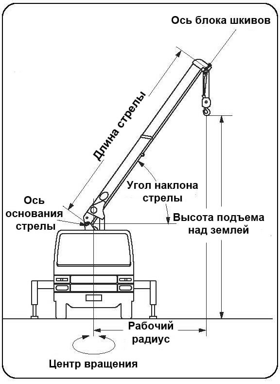
Working radius
The horizontal distance from the axis of rotation of the boom to the center of the hook.
Arrow length
This is the distance from the base of the arrow to its head.
Boom Angle
The angle formed by the arrow and the horizon.
lifting height
Height from ground to hook.
Outrigger extension (non-reversible)
Outriggers allow you to keep the crane-manipulator, during operation, in a stable position.
They can be set to three positions: minimum, medium and maximum.
Outriggers consist of two parts: horizontal and vertical.
The crane-manipulator works with the horizontal parts of the outrigger extended by the required amount, and with the ver-
tic parts to support the vehicle.
Boom section extension order
All boom sections extend simultaneously. The marks are applied to the intermediate sections of the boom.
When they appear, the determination of the carrying capacity of the CMU is carried out in relation to the extended given section to the full length.
Cargo height characteristics
Designed to determine the working radius, lifting height (lowering depth) of the hook relative to the level of the support
surface, depending on the length of the boom and the angle of its inclination and vice versa.
Although point A and point B follow a path along a certain working radius, point A refers to the angle of the boom, and point B to the rise of the hook above the surface. The working radius does not include the boom deflection caused by the load. Remember that the actual working radius when lifting a load will increase as a result of boom deflection.
Location of control devices

Automatic accelerator
CMU is equipped with an automatic accelerator to control the speed of lifting the boom, raising and lowering the hook, telescoping the boom, and turning the column.
The speed of the CMU varies in the range from slow to high, depending on the deviation of the lever from the neutral position.
Auto accelerator control
neutral position
Lever position before operation.
slow speed
When the control lever is in this range, the CMU operates at a slow speed.
High speed
When the control lever is moved all the way to the end position, the engine speed increases and the CMU operates at an increased speed. The lever is connected to the accelerator.
Stop
Release the control lever, it will return to the neutral position and the engine speed will decrease. The operation of the CMU will automatically stop.
Hand accelerator
Using the throttle lever
Using the accelerator
The speed of the CMU can be adjusted using the accelerator lever.
Idle Speed Adjustment The throttle lever is used to change engine speed, warm up the engine, and monitor load operation with a load indicator.
Before starting and finishing the operation of the CMU, set the accelerator lever to the minimum speed position, this will avoid jerks during operation.
★Before using the auto throttle, set the manual throttle lever to the minimum speed position.
★After the end of the CMU operation, the accelerator lever must be in the minimum speed position.
Note
Use the hand throttle lever to warm up the oil and set the operating speed to suit you.
Sound signal
Before starting the operation of the CMU, press the signal on button located on both control panels.
The sound signal will warn people who are in the working area of the CMU, next to the load or on the trajectory of the movement of the load about the start of work. The signal sounds as long as the button is pressed.
Hook lift limiter
1. Purpose of the hook lift limiter
Automatically stops the operation of the CMU and signals the approach of the hook to the boom, preventing the hook from hitting the boom head.
Principle of operation
Before starting the work of the CMU, turn on the hook lifting limiter.
If the alarm sounds while lifting the hook or extending the boom, stop this operation immediately and lower the hook. After finishing work, turn off this device.
★Hook lift limiter will not work if it is turned off. Before starting work, make sure that it is turned on and that a warning sound sounds when the hook raises the weight of the hook lift limiter.
★The length of the cable is normalized by the rules and related instructions, do not shorten it as you wish.
★If the electrical wire coming from the hook lifting limit switch breaks, the alarm will block the operation of the CMU.
Contact the Service Center for repair.
Working principle of the hook lift limiter (for Uni-hook)
Appointment of automatic stop lifting hook
If the hook raises the hook lift limiter weight, the buzzer will sound and the hook lift, boom up and boom extension will stop automatically. In this case, it is necessary to lower the hook, retract or lower the boom
until the sound signal is turned off.
★ The viscosity of the oil in the hydraulic system increases significantly in winter or at low temperatures environment. Under these operating conditions, work steps start and end with a time delay. This is not a malfunction. Warm up the hydraulic system by running the CMU without load at idle engine speed. During the lowering of the load after
automatic stop, the weight of the load will not be displayed on the load moment indicator.
★ When the buzzer sounds and the hook is below the weight of the hook lift limiter, check that the weight of the load to be lifted corresponds to the load chart.
Actions in the event of a malfunction of the automatic stop lifting of the hook
If the control of the CMU became impossible due to the failure this device, follow the steps below
Step 1
Move the auto stop switch to the off position. In this position, all operations will be available.
Step 2
If after completing the first paragraph of the CMU it still does not work, follow these steps:
Disconnect the power wire located under the control valve.
★ Do not disconnect the power cord when using the radio control. Refer to the instructions for the operation of the CMU with radio control.
Step 3
If the CMU does not work even after completing the second paragraph, do the following:
Loosen the nut on the unloader valve (located at the top of the control valve) and tighten the adjusting screw until it stops.
This operation will bring the loader crane to the transport position by means of the control levers.
★ After bringing the CMU to the transport position according to the above method, be sure to contact
Boom angle indicator (with capacity scale)
The pointer shows the permitted lifting capacity depending on the length of the boom and its angle of inclination.
1. Load capacity
The arrow indicates the permissible lifting capacity according to the length of the boom.
2.Boom Angle
The deflection of the pointer indicates the angle of the boom.
★ According to the load capacity scale, the permitted load capacity is determined, for which the CMU is designed with the maximum extended outriggers, but without taking into account its stability.
★ The value on the capacity indicator may vary depending on the length of the extended boom and the workload of the loader crane
★To ensure safety, when the boom section is half extended, use the scale reading corresponding to
full extension of this section.
When the second section is extended, use the reading for (2.3t).
When the 3rd section is extended, use the reading for (1.45 t).
When the “ ” mark is visible on the side of the 3rd section, use the section readings (0.95 t).
★ When lifting a load, the working radius increases as a result of the deflection of the boom. Set the angle of the boom so that the hook is at its maximum
slightly close to the inside of the boom.
Load indicator
Shows the weight of the lifted load.
Read the scale indications in accordance with the applied hook-and-rope suspension.
Note The load capacity indicator can be rotated around its own axis.
Rotate the capacity indicator to a comfortable position for easy reading.
On the dial is located
A and B scale for 6-wire hook suspension system;
Scale for single wire hook suspension system.

★ The load capacity indicator only shows the weight of the load when the load is being lifted.
★ The value of the load weight determined by the capacity indicator is an approximation
To measure the weight of the lifted load, follow the recommendations below. Compare the load weight reading with the value on the indicator. The load indicator has two arrows. Determining the weight of the load is possible by any of the two arrows: scale (A) for the red arrow and scale (B) for the white arrow.
1. Reduce engine speed.
2. Adjust the engine speed so that the arrow on the load capacity indicator points to zero (0) when
lifting hook without load.
3. Consider the case when lifting a load using a 6-wire hook suspension system and with three sections of the boom extended.
.
The load capacity scale shows that the CMU can lift a load of up to 1.45 tons (point "B", position (a), Fig. 1).
4. Read the “B” scale reading (position b) while lifting the load approximately 30 cm. The load indicator shows the actual weight of the load as 1.2 tons. This means that the CMU has a load capacity margin of 0.25 tons.
Checking CMU safety devices
1. When, when lifting a load, the indication on the load indicator indicates an excess of load capacity, then the crane-manipu-
The lator may be damaged or overturned. In this case, move the loader crane closer to the load to be lifted so that
to reduce the working radius. Operate CMU within the rated load.
2. When the capacity indicator reading is less than the rated load in the chart, the load can be lifted from its original position.
hook lock
Prevents the suspended load from slipping off the hook.
Automatic stop of the unwinding of the cargo rope (holding the cargo rope on the drum of the cargo winch).
Designed to disable the operation of the cargo winch in the "unwinding cargo rope" mode, when the cargo
winches, the number of cargo rope decreased to three turns.
Load moment limiter
To prevent the CMU from destruction and (or) overturning, they are equipped with a load limiter (limiter
load moment), automatically disabling the mechanisms for lifting the load and changing the reach when lifting the load, the mass of which exceeds the permissible load capacity at a given reach.
When lifting a load that is 90% of the maximum weight for that boom reach, an intermittent sound will sound.
sound signal. If the load moment increases further and amounts to 100% of the maximum allowable for a given boom outreach, then the mechanisms for lifting the load, increasing the outreach and lowering the boom will automatically turn off, i.e. those operations that will lead to an increase in the load moment will be unavailable. After the action of the load limiter, it is possible to lower the load or turn on other mechanisms to reduce the load moment.
Safety valves
Safety valves are installed on the pressure line of the pump in the hydraulic system of the CMU, designed to automatically protect the process system and pipelines from an unacceptable increase in pressure of the working medium.
1. Operation of the loader crane without an additionally installed temperature switch is PROHIBITED.
2.Before starting work, make sure that the temperature switch is working and turned on.
3. The operation of the crane-manipulator at an ambient temperature below -20 0 C is prohibited. This device is designed to limit operation at low ambient temperatures.
4. “For the purpose of safe operation, the owner of a loader crane is obliged to carry out the following organizational measures:
During the operation of the crane-manipulator, appoint by order from among the full-time certified employees responsible for the safe performance of work with the following duties assigned to him:
Ensuring compliance with the requirements of clause 5.5 of PB 10-257-98 for the performance of work (the deadline is permanent);
Conducting shift-based briefings for personnel involved in the operation of the crane-manipulator, and ensuring the safe performance of work (the deadline is before the start of work with an entry in the logbook);
Checking the functioning of the temperature relay in accordance with the provisions of the Operation Manual (the deadline is before starting work). The CMU operator, after receiving a warning signal about a decrease in air temperature, must take the following measures:
lower the load on the supporting surface and ensure its disconnection from the load gripping body;
Notify the person in charge of stopping the operation of the loader crane.
5. Ensure the operation of the crane-manipulator and the performance of work in accordance with Sec. 5 PB 10-257-98.
6. When the ambient air temperature reaches minus 20 0 C, all work using a crane-manipulator must be stopped. The resumption of work is possible no earlier than 6 hours after the air temperature rises above minus 20 0 С.
7. After the loader crane has been in ambient conditions with an air temperature below minus 30 0 С, before the resumption of work, the loader crane must be subjected to an expert examination, including a full technical examination carried out by a specialized organization. The results of the technical examination must be presented in the form
conclusions of industrial safety expertise with a mark in the passport of the crane-manipulator.
8. The function of monitoring the implementation of these measures shall be entrusted to the person responsible for maintaining the crane-manipulator in good condition.
Turning on the pump
Procedure
Checking the supporting surface on which the crane is installed
Make sure that the surface on which the crane is placed is firm and level.
Loader crane installation
Engage the handbrake.
If the loader crane is standing on a slope, additionally use brake shoes.
Checking the position of the control levers
Make sure:
the accelerator lever is set to the “low speed” position;
CMU control levers are in the neutral position.
Car checkpoint check
Engage the vehicle in neutral.
Engine starting
Start the engine.
Turning on the PTO
Depress the clutch.
Pull out the PTO engagement handle (or press the PTO engagement button).
Slowly release the clutch.
Check that the PTO enable lamp lights up.
★ Do not turn on (turn off) the PTO when the clutch is not disengaged
Turning on the hydraulic pump
The pump automatically turns on after switching on the PTO.
★In the cold season, it is necessary to warm up the oil in the hydraulic system at low speed and without load.
★The viscosity of the oil at low temperature is too high, which may damage the pump and hydraulic system of the CMU,
if you start working at high speeds without preheating the oil
★Loader crane operation without outrigger installation is strictly prohibited.
★When installing the outriggers on a shaky or uneven ground, install plates (such as metal plates or wooden shields) under the outrigger plates to prevent the outriggers from sinking when lifting the load.
★ Ensure that safety rules are followed when extending the outriggers to avoid injury and accidents.
★Installing a crane-manipulator on a supporting surface that is not sufficiently dense and even may cause it to tip over.
breathing.
Outrigger installation procedure
Rotate the locking lever to unlock the outriggers.
To release the outrigger, pull the stopper towards you and turn it clockwise.
After extending the outrigger, rotate it to reverse side so that the pin locks the outrigger.
With the intermediate extension of the outrigger, the first mark will be visible on the horizontal beam. To extend the outrigger
to the maximum width, pull out and turn the stopper again.
After the outrigger is fully extended, a second white mark will be visible on the side of its horizontal part.
Make sure that the stopper pin is inserted into the side hole of the outrigger and that the outrigger is securely locked.
★ Extend the outriggers to the maximum width when operating the crane
Outrigger management.
The vertical parts of the outriggers can be extended simultaneously or in turn.
Extend: Move the lever to the "EXT" position to extend the vertical parts of the outrigger.
Retract: Move the lever to the "RET" position to retract the vertical parts of the outrigger.
Stop: Return the lever to the neutral position to extend or retract the vertical parts of the outriggers to stop.
Auto Throttle The speed at which the outriggers extend and retract depends on how far the outrigger control levers are moved from the neutral position.
Use the auto throttle in conjunction with the manual throttle
Since the change in speed by the automatic accelerator, depending on the brand of the car on which the CMU is installed, may
be insufficient, use the hand throttle lever if necessary.
Use the outriggers to adjust the position of the crane-manipulator so that it is level and the front wheels slightly
touched the base surface.
★ Set the outriggers so that the front wheels lightly touch the ground
When you release the levers, they will automatically return to the neutral position.
Changing the angle of the boom
★ A sudden movement of the load during its lifting causes an increased dynamic load on the crane - manipulator, which can lead to its damage or overturning. Move the control levers slowly and smoothly.
★ The more extended the boom, the greater the speed of the load.
When working with the extended boom, move the control levers especially smoothly and slowly.
★ When the boom is lowered, the working radius increases, and the load capacity of the CMU decreases in accordance with the load capacity table.
Observe the capacity indicator to confirm safe operation before lowering the boom.
Climb: Move the lever to the "RAISE" position to raise the boom.
Lowering: Move the lever to the "LOWER" position to lower the boom.
Stop: Return lever to neutral position to stop boom movement.
Automatic accelerator
When the control lever is moved to "RAISE" or to "LOWER" the engine speed increases and decreases as the lever returns to the neutral position.
The change in engine speed by the automatic accelerator may be different on different car models, so use the manual accelerator to adjust the speed.
Lifting and lowering a load
★ Constantly watch the hook. Hitting the hook on the top sheave of the boom can damage the cable, block at the boom head and cause the load to fall.
★ Make sure the hook lift limiter is turned on.
Raising: Move the lever to the "UP" position to raise the hook.
Lowering: Move the lever to the "DOWN" position to lower the hook.
Stop: Return lever to neutral to stop hook movement.
Automatic accelerator
When the lever is moved to "UP" or "DOWN", the engine speed increases automatically.
When the lever is returned to the neutral position, the speed decreases.
Use the auto throttle at the same time as the manual throttle
The change in engine speed by the automatic accelerator may be different on different car models, so use the hand throttle lever to adjust the speed of operation.
★Lowering the hook without a load or with a load on the ground weakens the winding of the load rope on the drum, which can lead to uneven winding and shortened life.
★ When working below the ground, make sure that there are at least 3 turns of rope on the cargo winch drum.
★If the first layer of the rope is wound unevenly, then the second layer, wound on top of this layer, may fall between the turns of the first layer, which will lead to uneven winding and further jerks during operation.
When the rope is completely unwound, wind it slowly, tightly and evenly coil by coil.
★If the temperature of the oil in the hydraulic system is 80ºС or more, the operation of the CMU must be stopped!
The oil temperature will rise sharply if the lifting and lowering operations are repeated several times within a short time, especially at high altitudes.
Approximate oil temperature can be obtained by organoleptic method:
70 ºС You can touch the oil tank (lower part) with the palm of your hand and hold for 3-4 seconds
8 0 ºС You can touch the oil tank with your fingertips and hold for 1-2 seconds
9 0 ºС At the moment your hand touches the oil tank (lower part), you pull your hand back on reflex, due to the high temperature
boom swing
★Perform boom swing at low vehicle engine speeds.
★Start and end boom turning operation at low engine speed.
Sudden movement of the control lever while handling a load can cause it to sway and collide with nearby objects, which could damage or tip over the loader crane.
★ Swinging the lifted load increases the working radius, which leads to an overload of the loader crane.
★When extending the boom at a low angle of inclination, be careful, because. the lifting capacity of the crane-manipulator is sharply reduced due to the rapid increase in the working radius.
★Considering the above, make turns smoothly and at low speeds.
When moving the load "above the cab of the crane", from the position "back to side", "from side to forward" or "from side to back", the crane is unstable. In these cases, when turning the boom, keep the lifted load as close to the ground as possible.
Clockwise Rotation Move the boom swivel lever to position to rotate the boom clockwise.
Counterclockwise Rotation Move the boom swivel lever to position to rotate the boom counterclockwise.
Stop
Return boom swing lever to neutral position to stop boom swing.
Automatic accelerator.
When the control lever is moved to the or side, the engine speed of the crane - manipulator increases in accordance with the amount of deviation of the control lever from the neutral position.
Use the auto throttle at the same time as the manual throttle
The change in engine speed by the automatic accelerator may be different on different car models, so for
to set the desired operating speed, use the hand throttle lever.
★Turn on the warning horn before turning
Folding outriggers into transport position
★ Only retract the outriggers after the boom is in transport position!
★ If the outriggers are not handled with care, there is a risk that your fingers may be pinched, so use one hand
hold the lever while pushing the outrigger with the other hand.
★ To fold the outriggers, press the button on the outrigger and slowly push it in until it stops.
Secure the outrigger with the lock lever.
Move the outrigger control levers to the "RET" position to retract the vertical parts of the outrigger.
★You can retract the vertical parts of both outriggers at the same time
After retracting the vertical parts of the outriggers, press the key on the outriggers, slide the horizontal parts of the outriggers to the stop and release the key. A blue mark must be visible on each outrigger key.
★Make sure the vertical outriggers on both sides are retracted and each locking lever is unlocked before pushing the horizontal outriggers in.
After all outriggers are removed, check
The vertical parts of the outriggers are fully retracted.
The blue label must be fully visible on the keys.
The horizontal parts of the outriggers are securely fixed with a locking lever.
Note
A fully visible blue mark indicates that the horizontal parts of the outriggers are securely locked.
Rotate the locking lever to lock the horizontal part of the outrigger.
Note
Turning the locking lever prevents spontaneous extension of the horizontal part of the outrigger.
Bringing the crane-manipulator into the transport position
★Before driving, make sure the hook, boom and outriggers are in transport position and securely fastened.
★Make sure that the outriggers are fully retracted and securely locked from unintentional extension. Blue labels are visible on the outrigger keys.
★Make sure the outriggers are locked with the locking lever.
★The movement of the crane-manipulator with an insufficiently firmly fixed boom, outriggers and hook may cause an accident, damage to the parts of the CMU or hit the vehicle on the roadway.
Bringing the crane - manipulator to the transport position, perform in the following sequence:
Fold up the arrow
Set boom to over cab or over body position.
The boom should be in position where both yellow marks are aligned.
Lower the arrow to the stop.
Pay attention to the fact that in the transport position, when the crane-manipulator is moving, the hook does not reach the cab of the car,
whether the boom is installed in the “above the cab” position and to the body, if the boom is installed in the “above the body” position.
Moor the hook in the intended place of its attachment.
Pull the hook up to tension on the hook.
★ Do not overtighten the hook when the hook is attached to the front of the loader crane.
This may cause the vehicle frame to sag or damage the bumper.
Inspect each vertical and horizontal part of the outriggers.
Next, assemble the front outriggers in accordance with the paragraph "Folding the outriggers into transport position".
Make sure the throttle control lever is in the minimum speed position.
Turn off the hook lift limiter.
Depress the clutch pedal, disengage the PTO and slowly release the clutch pedal.
Make sure that the PTO enable indicator light goes out and the PTO itself is disabled.
Now the car is ready to move.
★ Failure to disengage the power take-off while the vehicle is moving will shorten the life of the pump
★CMU before commissioning must be subjected to partial technical certification in order to establish that
it is in good condition, providing it safe work. CMU, which is in operation, is subjected to periodic
technical certification:
- partial - at least once a year;
- full - at least once every three years.
★In order to avoid accidents, when carrying out maintenance, warning signs must be posted on the control levers.
tablets.
★Untimely replacement of consumables may cause damage. In this case, the warranty service of the CMU
will not be carried out, even if the warranty period has not yet expired.
Periodicity Maintenance CMU must be observed under any operating conditions and at any time of the year.
★ If any malfunctions or abnormal functioning of the CMU equipment are found, contact the service center for
completion of repair work.
★ Keep your crane in good condition, always ready for use
Washing
Keep your CMU clean. Sand and dust can cause accelerated wear.
Do not wash the CMU with a high-pressure water jet to prevent water from entering the electrical and hydraulic system, which may lead to
interfere with its normal operation
If the mounting bolts securing the bearing are broken, then an accident from the overturning of the CMU or its damage is possible.
Check at least once every 6 months for the presence and torque of the mounting bolts.
If the slewing mechanism makes an unusual noise during its inspection or operation, or there is a gap in it, contact the UNIC service department for diagnostics and repair of the CMU.
Checking bolts on the inner track
1. Remove the cover.
2. Check each bolt by turning the boom so that all the bolts in turn are visible in the window.
3. After checking, close the lid
Oil filter replacement
The first filter change must be carried out no later than three months after the start of operation. In the future, the filter is changed at least once a year. When changing the oil in the hydraulic system, the filter must be replaced.
How to install a new filter
Clean the seating surface of dirt, oil and other foreign matter.
Lubric the filter gasket with a thin layer of oil.
Screw on the filter by hand.
Replacing the cargo rope (for lifting a load)
The cargo rope is a consumable item. It is damaged or torn after prolonged use. The safety of the CMU depends on the timely replacement of the rope.
Replace the load rope according to the following criteria.
Replacement Criteria
1. A rope in which the number of broken wires (except filler wire) reaches more than 10% of the total. Replace group
call rope if more than 15 wires are broken.
2. The cargo rope has become knotted.
3. A rope whose diameter has decreased by more than 7% of the normal diameter. For example: Normal rope diameter is 8mm, replace
it if its diameter has become 7.5 mm or less.
The type of rope and its length are indicated in the passport for CMU
4. A load rope that has been deformed and/or heavily rusted.
★ Replace the load rope if it falls within one of the above criteria.

★ When changing the load rope, wear gloves
To change the rope, study the hook block reeving diagrams.
Rope fixation
Winch drum
The end of the rope in the cargo winch drum must be fixed as shown in the figure.
Pay attention that the end of the rope does not come out of the drum.
In order to avoid incorrect winding of the rope on the drum, it has recesses (guides) in order to
wound with the necessary tension, forming the first layer.
The second layer is wound on the first layer so that the rope lies in the grooves formed by the rope of the first layer.
Rope fixation order
Pass the rope in the direction of the arrow, through the wedge as shown in the figure. The distance from the clamp to the end of the rope must be at least 40 mm.
If the rope is fixed incorrectly, its service life will be less than the standard.
Remember to install the wedge and rope clamp.
CMU boom lubrication
How to lubricate the column and cable of the crane manipulator (CMU)
AIMOL-M Slidestop 68
Guide oil
Non-toxic oil specially formulated for the lubrication of slideways.
Advantages:
- Does not cause corrosion of both metal and non-metal parts
- Excellent load capacity
- Very good corrosion protection
Application:
The oil is used to lubricate the booms of telescopic cranes by brush, roller or spray. Also suitable for lubrication and corrosion protection of hydraulic cylinders.
Typical characteristics:
Slide top 68
Kinematic viscosity at 40°C, cSt: 68
Kinematic viscosity at 100°C, cSt: 8.6
Operating temperature range: -25 to +190°C
The most important error codes of the new safety device
E-05 ( system error) you need to reload the block
E-06 (system error) it is necessary to reboot the unit (if it constantly appears after a reboot, the unit must be definitely changed)
E-08 (boom angle sensor error)
E-09 (arrow reach sensor error)
E-10 (safety device calibration not completed)
E-11 (load sensor error)
If there is at least one error, the CMU will not work. During normal operation, the display should illuminate on.
if everything is fine, but the CMU still does not work, you need to check the emergency stop buttons, they may be pressed.