
Connecting a generator to a country house network: diagrams and connection methods
Depending on the model of the autonomous power supply device and the input shield circuit, the connection of the generator to the network of a country house may differ slightly in details. There are known differences between manual and automatic start, the nuances of connecting single and three-phase generators, but in general, if you have minimal skills in working with electrical circuits, you can do everything yourself. Well, if you understand the principles of operation of an electromagnetic starter and a relay, then you can set up autostart and a conventional generator, which otherwise would have to be constantly started with a key.
"Emergency" connection methods and their disadvantages
Usually, “fire” methods are used in cases where, for some reason, it is impossible to use the generator directly - you need to turn it on to your home network urgently, and there is no time to mount a separate connection scheme.
A specialist from a simple layman, among other things, is distinguished by knowledge of the causes of prohibitions - this is what allows you to bypass them at the right moments: to do something not according to the rules, but to get the desired result. Just do not forget the platitudes - electricity does not forgive mistakes, which means that you need to calculate your actions several steps ahead in order to exclude all possible overlays.
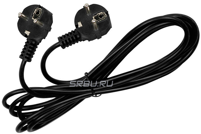
Connection via socket
The most common of the "fire" ways to connect a generator to a house is to plug it into a socket, for which you buy or make your own "carry" with plugs at the ends.
The principle of using such a connection becomes clear if you look at the standard home wiring diagram. Indeed, if a current source is connected to one of the sockets, then voltage will appear in all parts of the circuit.
If there is no three-position switch at hand, then it is temporarily possible to make a two-position changeover device from two two-pole automata. It is advisable to take them from the same manufacturer and denomination so that the sizes match. The machines must be installed side by side, but one of them must be turned upside down, and the keys fastened together - for this, the manufacturers provide holes for the pins.
A person who understands electrics can build such a device from four single-pole automata - do not turn them over and switch each one individually. But if someone other than him will start the generator, then it is better to take care of the "fool protection" right away.
The switch itself is installed near the generator. This is most convenient, since its start-up is carried out in a certain order: the generator itself starts first, and when it warms up, the load is connected to it.
So that the generator does not work in vain, after turning on the electricity on the main line, it is necessary to make a tap for the signal lamp and place it in a conspicuous place. So that it does not shine all the time, then it must be connected through a switch. If there are fears of forgetting to turn it on, then you can add an automation element by connecting the lamp through any normally open contact of the starter. The whole scheme for connecting the generator through a toggle switch and with a signal lamp is as follows:
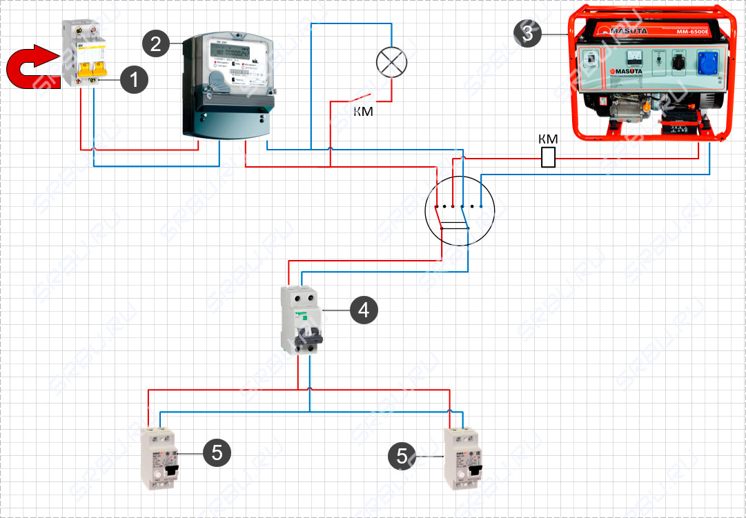
1. Introductory machine. 2. Electricity meter. 3. Generator. 4. Distribution machine. 5. RCD.
As long as there is voltage on the main line, the whole circuit operates as usual - the current passes through the switch and then goes to the distribution machine. When electricity fails, you must manually start the generator and switch the load from the house to it. When the generator is started, a current passes through the coil of the KM starter and its contacts close - the signal lamp is connected to the network and when electricity appears on the main line, the lamp will light up.
The simplest auto-switching scheme
So that every time you need to start the generator you do not have to click the switch, you can assemble the simplest circuit for auto-switching the current source. This is not an autostart system - its purpose is only to switch input between the main line and the generator, and starting and stopping the engine will still have to be done manually. The minimum required parts for this are two starters (contactors) - KM1 and KM2 with cross connection. They will involve power contacts (KMk) and normally closed (KMnz). In order for the generator to have time to warm up, it is additionally desirable to use a time relay.
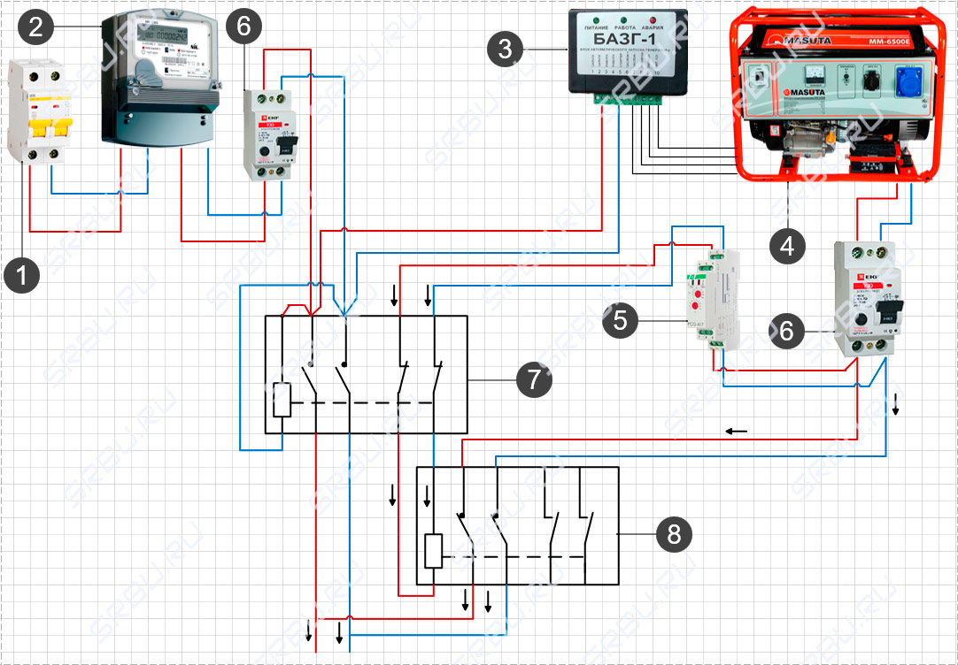
The figure shows such a scheme, how to connect the generator to the network at home - it works according to the following principle:
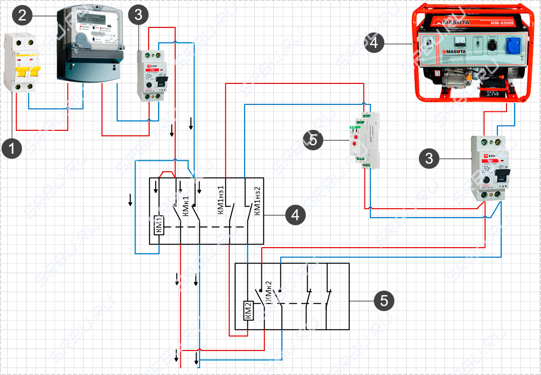
1. Introductory machine. 2. Electricity meter. 3. Distribution machine. 4. Generator. 5. Time relay. 6. Main input contactor. 7. Backup input contactor.
As long as there is electricity on the main line, the KM1 coil keeps the KMk1 power contacts closed and normally closed KM1z1 and KM1z2 open. When the electricity is turned off, the KMk1 power contacts open, and KM1z1 and KM1z2 close - now, when the generator is started, after the time for which the relay is designed, voltage will appear on the KM2 coil, the KMk2 power contacts will close and current will be supplied to the house from the generator.
When electricity appears on the main line, the KM1 coil is triggered - the contacts KM1z1 and KM1z2 open, de-energizing the KM2 coil. The power contacts KMk2 open, and KMk1 closes and the power to the house again comes from the main line. It remains only not to forget to turn off the generator itself.
Do-it-yourself generator autostart
If you have certain skills in electrical engineering, you can independently assemble a circuit that can start a generator without human intervention when electricity is lost on the main line. The main condition is that this requires a generator model that starts and stops with a key, since automating a starter that needs to be pulled by the cord is obviously a thankless task.
To understand the principle of operation of automatic start, you must accurately imagine the entire procedure that will have to be done to turn on the generator:
1. 1-2 minutes after the light goes out, open the engine choke and start it. A time delay is needed in case the light just blinked or turned off for a few seconds.
2. After another 2 minutes, when the engine is warm, transfer the load from the main line to the generator, then close the choke.
3. When electricity appears on the main line after 30-60 seconds, turn off the engine and switch the load from the generator to the main line
To implement this algorithm, you will need four time relays, four electromagnetic starters and magnetic pushers with limit switches, similar to servo drives that are used for the central lock of a car. The standard electromagnetic starter has a coil (KM), normally open power contacts (KMk), 2 normally open control contacts (KMnr1-2) and 2 normally closed control contacts (KMnz1-2).
In the figure, the general scheme for connecting a generator to a house with auto start - the principle of its operation is as follows.
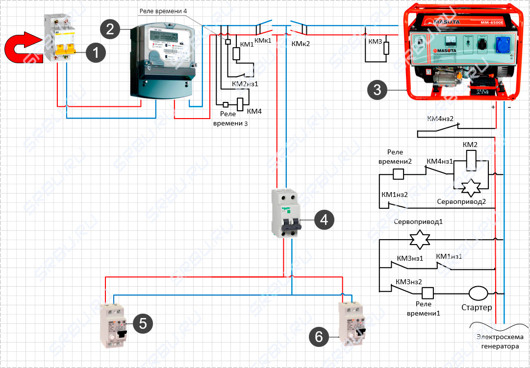
1. Introductory machine. 2. Electricity meter. 3. Generator. 4. Distribution machine. 5, 6. RCD.
In the event of a power outage, the KM4 coil ceases to hold the KM4nz2 contacts in the open state, which turns on the ignition of the generator. Also, the KM1 coil stops holding the KMk1 contacts - they open and now the line is disconnected from the home network. Normally closed contacts KM1z1 and KM1z2 are closed in parallel. They start the servo, which opens the engine air damper, and give an impulse to start Time relay 1 - in a minute, the key contact will close and the starter will start the engine.
The start of the generator causes the KM3 coil to operate, which opens the normally closed contacts KM3nz1 and KM3nz2, which stops the starter and de-energizes Servo-1. The parallel closure of the normally closed contact KM1nz2 sends a pulse to another time relay - after two minutes, Servo-2 will start, closing the air damper, and the KM2 coil will work, closing the KMk2 contacts, after which current is supplied to the house from the generator.
To ensure reverse switching, it is first necessary to open the KM2 coil circuit 1-2 minutes after the appearance of electricity and turn off the engine, for which time relay 3 and the KM4 starter are used, when triggered, the normally closed KM4nz1 and KM4nz2 open. When the KM2 coil is turned off, the normally closed contact KM2nz1 closes, which, after two minutes, turns on the KM1 coil through Time relay 4 - now the generator is de-energized and ready for the next start, and the power to the house comes from the main line.
This is just one of the possible launch automation options. For example, if desired, the circuit can be simplified by removing the time relay and air damper servos from it. True, this can only be done if the engine starts well, and in general all its components are well debugged.
The main disadvantage of any such scheme is that it controls the autostart of the generator, but will not be able to respond even to a minor emergency situation. For example, if the air damper is stuck, the engine will run at high speeds, and if the internal combustion engine itself malfunctions - if it does not start - at best, the battery will run out.
Auto start of the generator through the ATS unit
The purpose of such devices is to partially or completely exclude human participation in the operation of the generator. There are two main types of such devices. The first completely copies the auto-switching system, which works on two starters, but with the addition of an electronic unit for starting and stopping the generator. From the main power supply line, a low-current cable is supplied to it, through which the unit receives information about the presence or absence of voltage in the network. Depending on this, he gives the command to the engine to start or stop, and the switch between the input from the main line or from the generator is performed by the starters themselves. In general, this is the same system as the proposed scheme for self-assembly, but here you don’t have to invent anything - just install the finished block.
The disadvantage of such a block is the same - its purpose is only to start and stop the engine without additional protection.
The schema itself looks like this:
1. Introductory machine. 2. Electricity meter. 3. Block of automatic start of the generator. 4. Generator. 5. Time relay. 6. RCD. 7. Main input contactor. 8. Backup input contactor.
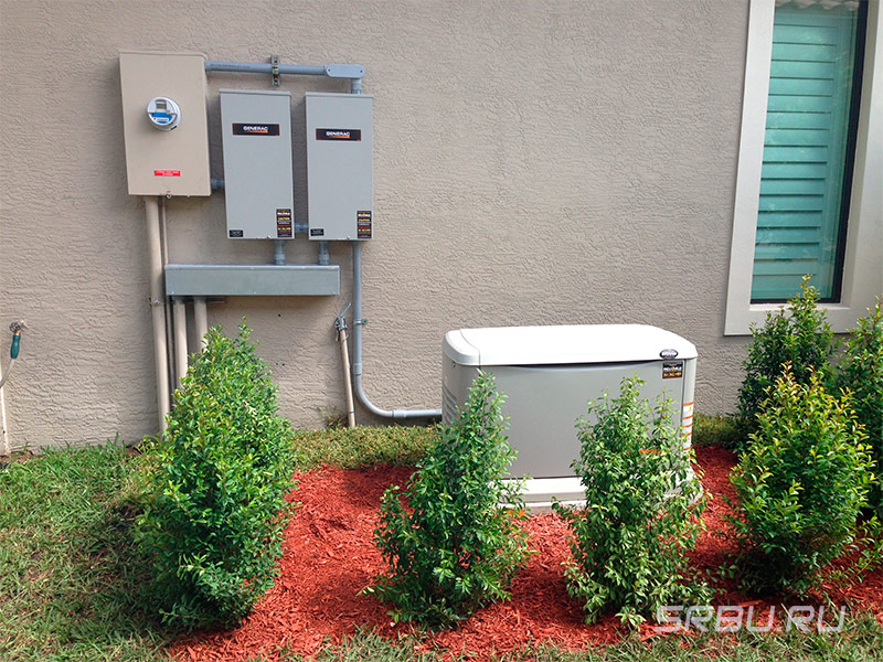
A more advanced version is a complex system controlled by microprocessor electronics. In general, it works in the same way as a homemade autostart system, but its main advantage is the presence of numerous sensors that control all aspects of the generator. If any equipment malfunction occurs, then the ATS unit will be able to respond adequately - not to torment the generator with attempts to autostart, but if there is a GSM module, send a malfunction message to the owner.
The ATS unit itself is mounted instead of the switchboard - this does not require much knowledge - you just need to connect the wires from the main line, the power and control cable from the generator and the output to the house.
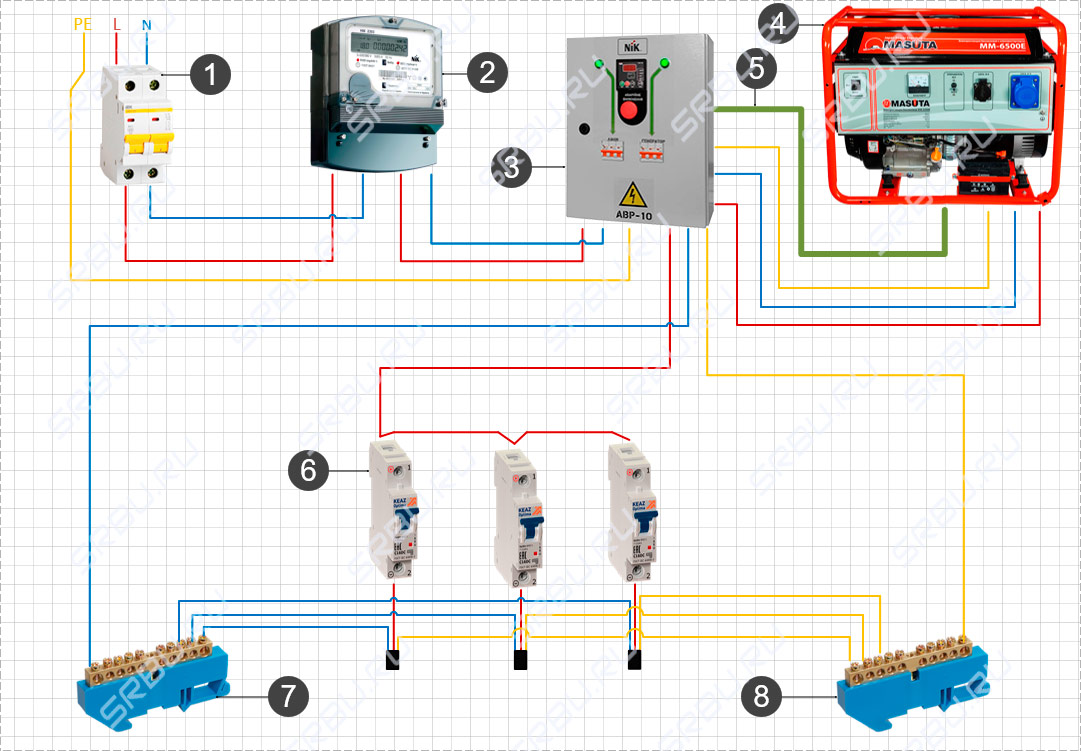
1. Introductory machine. 2. Electricity meter. 3. AVR. 4. Generator. 5. Control cable. 6. Automatic consumers. 7. Zero tire. 8. Ground bus.
Such a unit is a complex set of equipment and its cost in some cases may be equal to the price of a generator. Therefore, its purchase is justified only in the case of frequent power outages and for sufficiently powerful generators.
Difference between single and three phase connection
All connections, both in a single-phase and in a three-phase network, are completely identical, with the exception of the number of power wires. The only important nuance concerns the so-called control phase - if you connect a starter to the network, then its main contacts connect and disconnect power wires from the network, and power for the electromagnetic coil must also be taken from somewhere.
There are no problems in a single-phase network - there is only one phase and such a question simply does not exist, but in a three-phase network everything is somewhat more complicated - there are L1, L2 and L3. Without going into technical details, there is only one answer here - any of the phases can be used for control circuits, but only one. That is, if the KM1 coil is powered from the L3 phase, then the control of the remaining starters, the "Start" and "Stop" buttons must also be "hung" only on it. It is not difficult to do this - just note what color the wire is on the desired phase, and if the cable is with one-color cores, then stick or draw markers on them.
grounding
The very principle of operation of the generator involves the periodic occurrence of static electricity on its body, therefore, all permanently installed devices necessarily need a separate ground loop.
The ideal option is to create a full-fledged ground loop, but in general, you can get by in the simplest way, for which you need a metal rod 1.5-2 meters long, a steel bolt or clamp connection and soft copper wire. A bolt is welded to the iron rod, and the pin itself is hammered to the full length into the ground. The copper wire is screwed on one side to the bolt (or clamped with a clamp), and on the other side to the generator case - grounding is ready.
These are all the main ways to connect a gas generator to the network at home and possible nuances. The presented schemes will help determine whether it is worth installing autorun systems or it will be easier to get by with manual switching. Of course, when installing each individual generator, ATS unit or a home-made autorun system, additional questions may arise, but they will have to be solved in each case separately, depending on the model of the device and the home electrical circuit.