
Do-it-yourself grounding of a country house and system selection
Foreword
Grounding a country house is necessary to ensure fire safety. But in order to do the grounding of a private house with your own hands, you must first choose a suitable system for organizing this work.
Necessary tools and materials
 BulgarianDrillGround wireInsulating tapeIndicator screwdriverCrown for concreteround nose pliersSledgehammerwire cuttersPerforator bladeMetal cornerA hammerMetal shearsScrewdriversplierssoldering ironPerforatorGlovesadjustable wrenchWelding machineElectric testerelectrodes
Content
Grounding a country house is necessary to ensure fire safety. But in order to do the grounding of a private house with your own hands, you must first choose a suitable system for organizing this work. To date, there are several options for arranging a grounding and lightning protection system, their brief description, which is offered on this page, will help you make the right choice.
Today, the lack of grounding in residential buildings built several decades ago is a big problem. Since we are talking about the safety of a person and his life.
grounding- this is the connection of all conductive parts of the electrical network to the ground. The whole complex of measures for its installation is done with one goal: to divert the current that has arisen in an unnecessary place to where it will not harm anyone. It is a kind of pressure relief valve. It is of two types: the actual grounding and grounding. For example. Any modern washing machine is grounded. This means that the ground conductor is connected to all parts of the appliance that should not be energized: the body and parts of the internal fastening of the motor, drum, etc. If the washing machine is connected to a network that does not have a ground wire, then in case of any power failure voltage will appear on these parts and, when touched by a person, will shock. When grounding, the voltage will leave the case through the protective conductor and the residual current device (RCD) will instantly work, reacting to current leakage (when it is, of course, installed). Touching the device in this case does not threaten anything, since the resistance of the human skin is much greater than that of the conductor.
Lightning rod (lightning rod)- a good example of grounding, only between heaven and earth. The discharge hits a metal pin and, without affecting the house, goes into the ground. The lightning rod is included in the general grounding scheme.
Zeroing- this is the connection of parts of an electrical device that are usually not energized with a working zero. If a phase connection occurs with these parts, a short circuit will occur and the circuit breakers will operate. Less efficient than grounding.
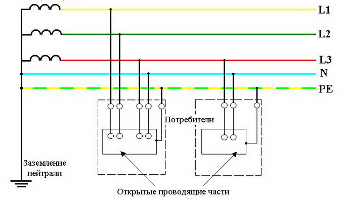
Types of grounding systems TN-C, TN-S, TN-C-S
For implementation in suburban housing construction, there are various types of grounding systems: TN-C, TN-S, TN-C-S, IT and TT. Further, by letter decoding, you can understand how the TN-S grounding system differs from the TN-C grounding system. Also in practice, a modern and more advanced TN-C-S grounding system is often used.
The first letter in the system designation determines the nature of the grounding of the power supply:
- T - connection of the neutral of the power source with the ground;
- I - all current-carrying parts are isolated from the ground.
The second letter determines the nature of the grounding of the open conductive parts of the electrical installation of the building:
- T - connection of the open conductive parts of the electrical installation of the building with the ground, regardless of the nature of the connection to the power source;
- N - connection of open conductive parts of the electrical installation of the building with the grounding point of the power source.
The letters following through a hyphen indicate the method of constructing the protective and working neutral conductors:
- C - the functions of these conductors are provided by one common PEN;
- S - functions of zero protective PE and working N are provided with separate conductors.
This system is used in private houses.
Currently, the TN-S grounding system in Russia is practically not found in the private sector. A separate earth conductor (PE) is not extended from the substation transformers to the consumer. Grounding is done independently using the TN-C-S or TT grounding system.
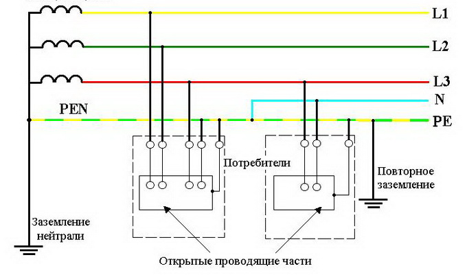
The TN-C-S system is the most common because it requires less effort to install.
The TT earthing system is used only if all the requirements established for it are met and the reason for the rejection of the TN-C-S system is given.
Grounding starts from the main ground bus (GZSH) installed in the input device (VU) or in the shield of the house. The diagrams show the difference between grounding from a VU or a home shield.
If grounding is done directly in the house, then when zero burns out on the line, for example, somewhere near a substation, the wire that leads from the pole to this house and, in general, the entire neutral in the building, will turn out to be zero. It should be remembered that on the line leading from the substation to a certain private house, there are still connections to other houses. The entire load that fell on the neutral wire of the power transmission line will, in this case, fall on the zero located in the house. If grounding is installed from the bus to the input device, then the load will fall on the wire that leads from the line to the bus, and it, as a rule, corresponds in cross section to the wire on the line.
Arrangement of lightning protection and grounding system TT
The TT earthing system is used only in private houses. The device of the grounding system and installation is fraught with some difficulties, first of all, the regulation of the power supply organization system: it must be tested and certified by a specialist from technical supervision.
Most often, many organizations offer to install a TT lightning protection and grounding system without intervention from the owner of the house, of course, without forgetting to charge a fee for its installation. If you try, you can do this work yourself, but after that you will have to check it and document it in technical supervision.
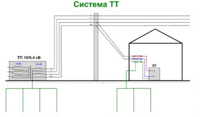
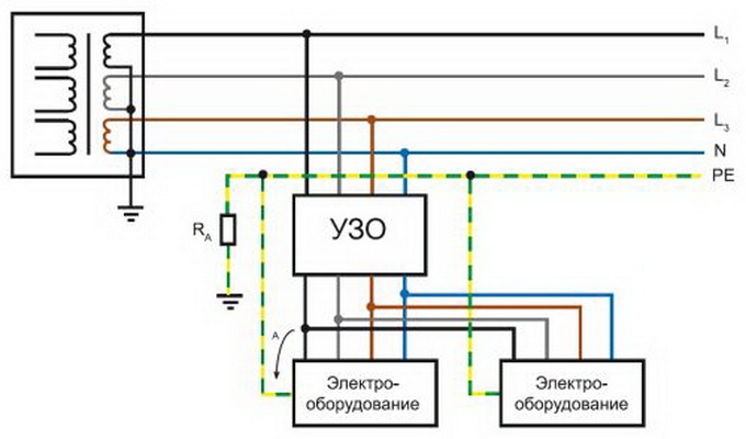
The TT system is very similar to the TN-S. The difference is that the ground conductor does not go to the substation to the ground electrode, but is located directly on the site next to the house. At the substation, the grounding system was made by specialists in accordance with all the rules for the installation of electrical installations (PUE). On a personal site, you will have to do the same.
When conducting a TT grounding system, the wire does not come into contact with zero and phase, but exists on its own.
The use of a residual current device with a CT earthing system is mandatory.
How to make grounding in the country with your own hands?
There are only two options for how to make grounding in the country with a full-fledged closed loop. The first of them is laborious, but you can do it yourself. The second will be done by specialists, but, of course, not for free.
Consider the first option: do-it-yourself grounding in the country house consists of a ground wire and a ground electrode. The ground wire must be with a core cross section equal to the cross section of the phase core of the cable laid in the house. This wire is connected to the ground bus in the home distribution box. All ground wires from electrical appliances converge to it.
A grounding conductor is a steel structure that equalizes the potentials in the event of a voltage appearing in the grounding loop. That is why it must be in contact with the ground.
So, we make grounding in the country, but first we determine the resistance of the soil, which structure and to what depth should be installed. Completely different cases when the earth is dry sand, and when it is wet black soil.
With the first option, you will need a very massive structure, with the second - a small reinforcing bar driven in shallowly. In order not to mess with the calculations, you can make a design that meets all the requirements in almost any conditions.
They take three corners with a length of at least 3 m and shelf sizes of at least 50 × 50 mm (you can use an ordinary pipe with a diameter of 16 mm and a wall thickness of at least 3 mm, so as not to break the top of the pipe with a sledgehammer). You will also need three pieces of a corner of 3 m with shelf sizes of 40 × 40mm.
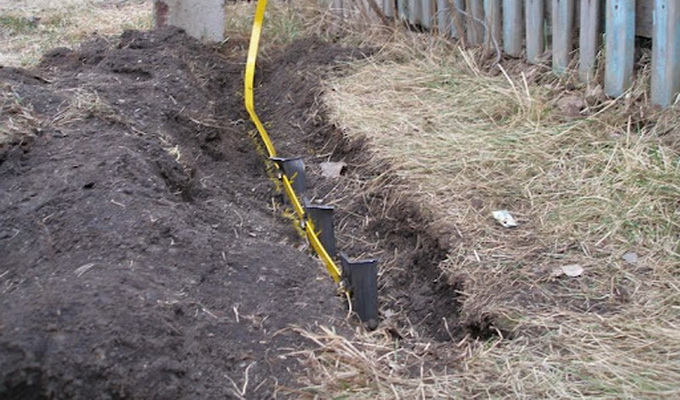
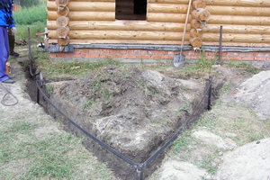
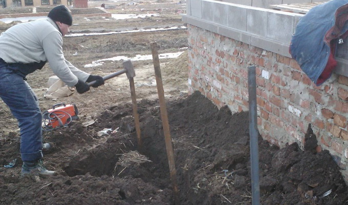
Then they dig a trench with a depth of at least 0.5 m and approximately the same width from the house to the place where the ground electrode will be dug in. In places where the pins will be driven in, holes are made the same depth as the trench - 0.5 m each. Grooves are dug between the holes, along which the corner connecting the pins will pass.
After that, a three-meter corner with the ends sharpened into a point is driven into the ground so that its end rises no more than 15-20 cm above the bottom of the hole.
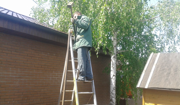
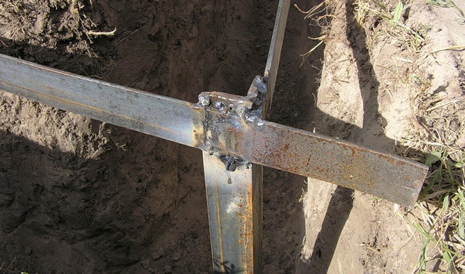
You will need a wide, stable ladder or goats to hammer a corner from them. After it is driven in to the desired depth, all three segments measuring 40 × 40 mm are welded together. The result is an equilateral triangle measuring 3x3x3 m.
It is not necessary to make the grounding conductor in the form of a triangle, you can hammer the corner with a line in a row. It is only necessary to observe the distance between the corners - it must be at least 1.2 m.
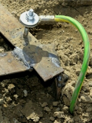
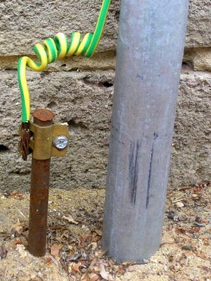
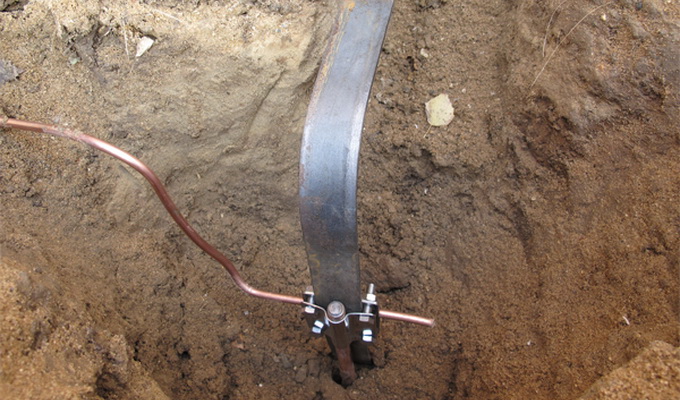
The top of one of the corners is pre-drilled for connection to the ground conductor using a bolt clamp. To do this, the end of the bare core of the grounding conductor is pressed into a lug with a hole suitable for the bolt. Then they dig in a trench and pits and install a sign indicating the place where the ground electrode and the conductor to the house are hidden, so as not to disturb it in the future during any work.
When performing work by a hired electrician, it is necessary to ensure that edible salt is not added to the soil near the ground electrode. This is done in order to reduce the resistance of the ground electrode, improving its contact with the soil. Allegedly, the grounding conductor must pass the resistance measurement test. In addition, salt lowers its freezing point. However, the saline solution will corrode the metal of the ground electrode in a few years, which will lose its properties.
After the ground electrode is installed in place, it is covered with soil, preferably with sand, in order to further facilitate access to the cable.
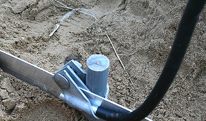
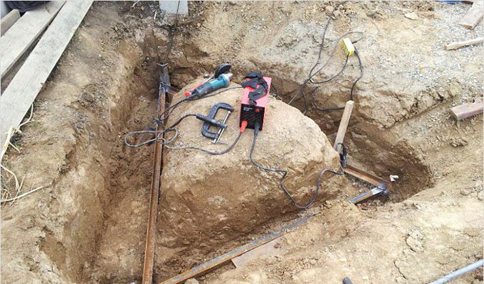
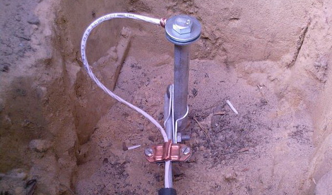
In the second option, you do not have to dig the ground and drive a corner into the ground. It uses a modular pin system. This is a recent invention and, admittedly, a very successful one. To create the largest area for soil contact with the ground electrode, a steel pin coated with copper is hammered to a depth of 20-40 m.
For the conditions of central Russia, this means that in almost any case such a pin comes into contact with groundwater, which sharply reduces its resistance. For a grounding conductor, this is one of the most important indicators. The convenience of this type of grounding is obvious: there is no need to dig a trench, a small hole 50x50x40 cm is enough. The only “but” is that it will not work to drive in such a ground electrode with a sledgehammer; for this, a puncher with a special nozzle is used.
A puncher with a conventional drill will not work, because it is necessary to work in shock mode without rotating the head.
The ground wire is mounted on the rod using a special clamp that comes with the rest of the equipment.
To what depth it is necessary to hammer in the ground, it is determined by measuring the resistance with a multimeter (a combined instrument that includes the functions of a voltmeter, ammeter and ohmmeter in the minimum set). These are quite complex calculations that only a qualified specialist can perform. They should not be produced independently, since the resistance will still be measured by a technician from the organization with their equipment - no one will take your word for it that the depth of the ground electrode is sufficient. You should know only the numbers that are the norm. For a three-phase network with a voltage of 380 V, the resistance of the ground electrode must be no more than 2 ohms, for a single-phase network with a voltage of 220 V - no more than 4 ohms.
However, you can make grounding without special measurements - you need to know the level of groundwater. A grounding conductor that reaches this mark will certainly meet the requirements.
In the case when the grounding system of the TN-C-S house is similar in terms of the grounding device to the TT system, there are not such strict requirements for it, since the grounded zero is located at the substation and is connected to the main ground bus in the input device or input distribution device.
But if the GZSH bus is located on the VU, then it is impossible to connect zero and ground in the future! Such a connection should be the only one in one area, according to the principle “either one or the other”, VU on a pole or ASP near the house or inside it.