
Drawing up a layout drawing. Making a master plan. Norms
A layout drawing is a drawing containing all the necessary data for transferring individual elements of a structure to nature.
A layout drawing is essentially an analytical expression of a master plan.
A layout drawing for a detailed layout project is developed on a topographic plan at a scale of 1:1000 or 1:2000 (1:500-1:2000).
The initial data for drawing up layout drawings can be obtained:
1) Graphically- this method is based on the determination of the required values according to the plan. The length of the segment is determined with a compass on a scale ruler, taking into account the deformation of the paper, or calculated from the coordinates of the ends of this segment., Determined according to the plan. The second method is convenient if the ends of the segment are located on different tablets. The directional angle of the lines is measured with a protractor.,
2) Analytically– here the alignment elements are determined analytically by solving the inverse geodetic problem. The coordinates of the points are given from the condition of compliance with the dimensions with a higher accuracy than the scale of the plan allows. The most accurate way.
The necessary layout data (angles, distances) are obtained on the basis of solving the inverse geodetic problem using the formulas:
where rn-r is the point of the desired direction
Yn,Xn – design point coordinates;
Er, Xr – coordinates of the geodetic grid point.
For control, calculate:
The analytical method is the most accurate, does not depend on the scale of the plan, is used when high design accuracy is required; Graph-analytical method is used quite often. This method is recommended when high accuracy is not required.
The analytical method for calculating alignments includes the following methods:
Method of rectangular coordinates - alignment elements are calculated relative to the tops of the construction grid, while the coordinates of the main points of the structure and the coordinates of the tops of the construction grid are set. This method is used if there is a construction grid on the site;
Polar coordinates method - alignment elements are calculated relative to geodetic control points, while the coordinates of the main points of the structure and the coordinates of the control points are set. This method is recommended to be used when it is convenient to break corners and significant linear distances on the ground;
Corner serif method - alignment elements (angles) are calculated relative to geodetic control points. In this case, the coordinates of the main points of the structure and the coordinates of the control points are set. This method is recommended to be used in the presence of insurmountable sections and obstacles on the site. Moreover, it is necessary to ensure that the angle satisfies the following conditions: 300< <1500.
The method of linear serifs. Alignment elements (lengths of segments) are calculated relative to geodetic control points. In this case, the coordinates of the main points of the structure and the coordinates of the control points are set. This method is recommended to be used when segments are broken on the ground, the length of which does not exceed the length of the measuring instrument.
3) In a mixed (combined) way - the method of preparing for the transfer of the project to the site is a combination of analytical and graphic methods.
As a rule, the coordinates of the staked points are taken from the plan, and the elements of the layout are calculated analytically to reduce the effect of deformation errors on the paper on which the plan is drawn up. The accuracy of the graphical method depends on the scale of the plan. The root mean square measurement error according to the length plan is determined by the scale accuracy: Ml = Δ l * M
where Δ l = 0.01 cm is the minimum distance that the human eye can distinguish;
M is the scale of the plan.
m'l \u003d 0.01 * 500 \u003d 5.00 cm \u003d 0.05 m (for 1:500)
m” l = 0.01*5000 = 0.5v (for 1:5000)
After determining the alignment elements, a layout drawing is made, which shows the reference points of the designed structure, design angles and distances connecting the reference points.
40. Layout drawing and its purpose
Stakeout work is one of the main types of engineering and geodetic activities. They are performed to determine on the ground the planned and high-altitude position of the characteristic points and planes of the structure under construction in accordance with the working drawings of the project.
The construction project is drawn up on topographic plans of a large scale. Determine the location of the designed structure relative to the surrounding objects and cardinal points. In addition, the topographic plan determines the general geodetic coordinate system that specifies the position of the characteristic points of the designed structure relative to this system.
Marking geodetic works (removal of the project in nature) is the process of finding the position of the points of the structure on the ground according to the coordinates specified in the project.
The results of the geodetic preparation of the project are displayed on the layout drawings. The layout drawing is the main document according to which layout works are carried out in kind, it is drawn up on a scale of 1:500 ... 1:2000, and sometimes larger, depending on the complexity of the structure. The layout drawing shows: the contours of the buildings and structures to be removed, their dimensions and the location of the axes, the points of the layout base, the layout elements.
The implementation of landscaping, landscaping and landscape design involves the development of a master plan, often called briefly - the general plan. A layout drawing (or plan) is its important component, on the basis of which the project is staked out.
Stakeout Drawing - Definition
A layout drawing is a part of a design set of general plan drawings that contains a graphical representation of information about the location of the designed structures, parts and elements in relation to existing support bases. For the correct preparation of the layout plan, it is necessary to follow the requirements of GOST 21.508-93. It establishes such a composition of the master plan drawings, which, in addition to the layout, includes:
- relief organization plan;
- a master plan for communications and networks;
- remote elements;
- plan for the improvement of the adjacent territory;
- plan of earth masses.
An important feature of the listed documents is the ability to combine several drawings into one, if the area is small. In the case of large-scale construction, on the contrary, it is allowed to divide one plan into several parts.
Often the question arises, what is the difference between a layout drawing and a plan? The layout plan is the same document as the layout drawing. Strictly speaking, this name is considered more correct, since it is the plan, and not the drawing, that is mentioned in the GOST. In practice, both names are actively used equally.
The layout plan (drawing) is used to place planning elements and projects on the ground. These include:
- Structures and buildings. The plan indicates the contours and points of intersection of the axes, as well as binding to existing landmarks;
- Planar structures:
- sidewalks, roads, platforms: the width, radii of curves and coordinates are plotted, allowing for snapping;
- elements of planning relief: ramps, slopes, retaining walls;
- drainage facilities;
- Small forms and equipment. The plan includes a list of small forms and equipment to be installed.
The north direction indicator, the existing red line, and any other conditional boundaries are also applied to the layout plan. The basis of the drawing is the alignment basis or geodetic grid.
Methods for drawing up a layout plan
There are two ways to draw up a layout drawing:
- Ordinate method. It is used for small areas without differences in the level of the relief. Binding of designed objects is performed using ordinates - perpendiculars. They are built from reference points, which are the entrances to the territory, the corners of the sites and other similar elements;
- The way of squares. Used for large areas. Constant geodetic reference points are used to bind objects. With their help, a grid of squares is created, relative to which the position of the designed elements is determined.
There are other ways to draw up a layout drawing, but they are much less often used in practice in modern conditions.
The layout plan (layout of buildings and structures) determines the position of all designed and maintained buildings and structures on the territory of the site being built up. In addition, it shows the situation and the terrain.
The construction geodetic grid, which is used to link buildings, must cover the entire layout plan. It is applied to the drawing in the form of squares with sides of 10 cm. The origin of coordinates is taken in the lower left corner of the sheet. The axes of the construction geodetic grid are indicated by Arabic numerals corresponding to the number of hundreds of meters from the origin, and in capital letters of the Russian alphabet: A - horizontal, B - vertical axes. Thus, OA is the origin of coordinates. 1A, 2A, FOR - horizontal axes; OB - the origin of coordinates. 1B, 2B, ZB - vertical axes.
For drawings made on a scale of 1:500, intermediate axes should be entered every 50 m. For example, OA + 50, 1A, 1A + 50.
When linking individual buildings to the alignment base (conditional line), the red line or to existing buildings, the construction geodetic grid is not applied.
On the layout plan, when depicting the contours of buildings, the blind area and entrance ramps, external stairs and platforms at the entrances are indicated. In two opposite corners of the contour, construction coordinates are applied for the points of intersection of the coordination axes of the building. For buildings of complex configuration or when they are located not parallel to the axes of the building geodetic grid - in all corners. For centric structures, the coordinates of the center and one characteristic point are indicated, and for linear structures, the axis coordinate or the coordinate of the beginning and end of individual sections.
Inside the contour of the building in the drawings, a level mark is applied in the form of an arrow according to GOST 21.101-97, and on the shelf of the leader line - an absolute mark corresponding to the conditional zero mark (0.000), i.e. level of the clean floor of the building.
On the layout plan, at the contour of buildings, the openings of gates and doors are depicted on the scale of the drawing, as well as the axes and coordinates of the axes of the gate.
At the coordinated points, the coordination axes are depicted and marked. The layout plan indicates:
- red lines, building lines and the boundary of the territory allotment;
- buildings and constructions;
- platforms for various purposes;
- sidewalks and paths;
- transport communications;
- fencing with gates and gates or a conditional border of the territory;
- arrow "south - north" and other necessary elements of the layout plan.
On the layout plan, if necessary, can be given: the explication of buildings for master plans of enterprises, or a list of residential and public buildings for master plans of housing complexes (Fig. 14.3.1. and Fig. 14.3.2.)
Figure 14.3.3 shows a fragment of the breakdown plan of the industrial building. The building is designed two-story (two dots in the lower left corner of the building). According to the general plan, this building has the third serial number (number three in the lower right corner).

The mark +110, 50, applied on the building plan, is conditionally accepted on all drawings of the buildings of this master plan as 0.000. The coordinates of the gate axis and the longitudinal axis of the road are also indicated. On fig. 14.3.4 shows a fragment of the layout plan of a residential and civil facility with dimensional reference.
The part of the project in which the elements of the relief of the territory are developed in detail is called the relief organization plan. Capital buildings and the area to be developed involve changes in the existing configuration of the surface of the site. Sometimes these transformations are very significant and are associated with the movement of soil masses, the construction of workings, embankments, retaining walls. The organization of the relief is usually optimized according to the criterion of minimizing the import or export of soil.
Terrain planning scheme
A well-done one will aim for zero-balance earthworks. Based on the topographic plan and the relief organization plan, a cartogram of earthworks is compiled. This diagram shows the difference between the existing terrain marks and those designed at the nodal points. This approach was used in landscape design before the spread of digital technologies.
Today, more and more often, a digital terrain model is being built and a digital model of the site being designed is subtracted from it. The principle is the same, but the level of clarity is higher, as is the detail of the situation. Although the excessive information content of three-dimensional models has a negative impact on practical tasks. To achieve the design positions of the relief, characteristic points with design elevation marks are fixed in nature.
Site layout example
This may require a layout plan.
Plan of sites and driveways
In general, such a plan is part of the information reflected in the master plan of the site. If these elements are designed separately when, then the plan of sites and driveways will be an independent drawing.
The plan reflects the configuration of the elements, the planned-altitude position of the characteristic points of the road surface is necessarily given. The layout drawing of roads and sites is carried out separately on the basis of the plan.
Read also
Planning and development of settlements
Landscaping and landscaping plan
Building or reconstruction ends with the planting of green spaces, the arrangement of flower beds, lawns and other elements adopted in garden and park design. This part of the project will provide detailed information on the placement of elements of improvement, recreation, sports.

Detailed landscaping plan
A landscaping plan, or planting drawing, is created on the basis of a relief organization plan and a road and site plan. Plantings, elements of arrangement are placed taking into account the designed relief, roads, platforms and sidewalks.
A layout drawing can help to bring out the actual position of the elements of the plan on the ground. For planting bushes and trees, a layout and landing drawing is drawn up.
What you need to know to take out a point
Any point of the plan is bound to a conditional coordinate system. Usually these are the axes of a building under construction. Distances along perpendicular axes allow precise positioning of a point. During reconstruction, landscape reorganization, work is carried out among existing buildings.  In this case, the point can be snapped from any existing element, such as a wall or corner of a building. Having made a layout drawing with plotted distances, you can begin to stake out points in nature. The callout is carried out by the method of polar or rectangular coordinates. In the first case, a radius equal to one of the distances is plotted from a given point.
Having done the same from another point of the site, the point of intersection of the circles is determined on the ground. It's not very accurate, but it's a simple method.
When making a point relative to the rectilinear faces of a structure, for example, the walls of a building, the distance in the alignment of the wall and the distance perpendicular to the alignment are plotted. This method is also not very accurate, since it is impossible to lay a perpendicular without special tools. But with the support of a layout plan, the job is easy to do.
How to do it right
The only correct method of transferring the points of the site plan to nature is their callout using the equipment used in construction geodesy and topography. Nodal and characteristic points are determined on the digital model of the plan and their coordinates are set. A layout plan with points prepared by geodetic equipment allows you to enter coordinates and elevations into the device.
A layout drawing is made only after drawing on the design plan of all design lines, designed objects and records on it of all segments (measurements) and angles necessary to transfer the project to nature.
The layout drawing is a technical document. It is compiled on the basis of applying the volume of work that can be completed in 2-3 days, then a new layout drawing is drawn up (in order to avoid damage - more than one for the entire period of work).
Only the necessary for transferring the project to nature is applied to the layout drawing:
· design boundaries;
the magnitude of the design angles and lines that need to be built or measured on the ground;
· points of geodetic substantiation, which are used when transferring the project;
· contours of the situation, facilitating the location of geodetic justification points on the ground or serving as a support for transferring the project;
Numbers and names of land holdings and land uses.
The layout drawing shows:
black ink existing on the ground borders, contours, inscriptions, conventional signs, rhumbs, line lengths;
· in red ink all projected boundaries, site numbers, geodetic data;
· projected theodolite traverses, auxiliary trunk lines and related geodetic data in blue ink.
It is better to record readings (measurements) on a measuring instrument on an accrual basis (to avoid errors, to increase accuracy), and even better - double data: both the distance between points and the length of an accrual total. The route is marked with arrows.
The more thoroughly the preparation for the transfer of the project is carried out, the faster and with less errors the field work is carried out.
Signs at the design points are installed in the alignment of the line on which the design boundaries are based. However, if the location of the sign falls on a road, in a ravine, swamp, etc., then the sign is placed away from the reference line, but on the design boundary.
With a sufficiently reliable geodetic justification for transferring the project, when repeated measurements, calculations and amendments to the dimensions of the sides of the sections are not required, measurements are usually performed quickly, only the setting of signs is delayed. Therefore, it is necessary that there be at least 2 - 3 pairs of diggers with well-honed shovels. They put up boundary markers at the points marked by the land surveyor in place
stakes. At these points, the land surveyor leaves signs, on them he writes down the numbers of the fields between which these signs are installed with oil paint. In order for the setting of signs at the marked points to be sufficiently accurate, along one line (in the alignment), the place for setting each sign is taken to the cross or to the alignment. To do this, at a distance of 2-3 m from the point marked with a stake, four thin pegs are placed, so that the place for setting the sign is at the point of intersection of the lines connecting them. After that, they dig a hole and put a sign in it, checking its position by pegs. Sometimes, instead of pegs, grooves are dug on the ground, and one of them, where the line between the inscriptions of field numbers should be directed, is dug another groove in the form of an arrow. Then the workers will be able to accurately place the sign, correctly orienting it in accordance with the inscriptions. The signs are dug in mounds 0.3 - 0.5 m high and 1.5 - 2 m in diameter. A ditch is dug around the mound, the earth from which is poured onto the mound. All boundaries between fields and plots, roads and cattle passes are plowed into one furrow.
A layout drawing is made only after drawing on the design plan of all the design lines of the designed objects and recording on it all the segments (measurements) and angles necessary to transfer the project to nature. It is a technical document, as well as the outline of a theodolite survey, is attached to the technical office work and indicates the order and correctness of the field work. It provides for such a procedure for transferring the project that will ensure the highest productivity of the contractor, reduce idle movements of the workforce and allow the work to be completed with the required accuracy.
Layout drawings are drawn up to the scale of the project plan only for those parts of the land use on which the project will be transferred within one to three working days (to avoid damage to the entire layout drawing in the field). If the project is simple, then the layout drawing can be drawn up schematically on a piece of paper.
Only what is necessary for transferring the project to nature is applied to the layout drawing: design boundaries; the magnitude of the design angles and lines that need to be built and measured on the ground; geodetic justification points that are used when transferring the project; contours of the situation, facilitating the location of geodetic justification points on the ground or serving as a support for transferring the project; numbers and names of fields and plots.
On the layout drawing, it is customary to depict in black the boundaries existing on the ground, the contours of the lands, conventional signs (significantly sparse) and the inscriptions of geodetic data related to the existing boundaries (points, line lengths), and in red - everything designed: boundaries, plot numbers, geodetic data. At the same time, it is better to show new (projected) theodolite traverses, auxiliary trunk lines and geodetic data related to them in a different color (blue, purple).
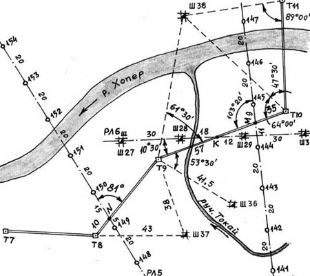
Measurements to the boundaries of the sections on the layout drawing (Fig. 6.3) are recorded on an accrual basis along the way, starting from one reference point to the next, near the design and final reference points. This is useful when placing a line on the ground. Firstly, it eliminates errors when summing line segments. Secondly, it makes the measurement process continuous from the starting point with a measuring tape or an electronic range finder (total station) when the reflector is moved along the line. Thirdly, obtaining a control reading at the end of the reference line, equal to its length, that it is along this line that the project is transferred to nature.
When compiling a layout drawing, they think over the route of movement when performing field work and mark it with index arrows (Fig. 6.3 and 6.4). At the same time, points are marked at which milestones will be installed for orientation when laying side passages and lines that serve as reference points for laying out other sections .